background image

Page 3

Maintenance and Servicing Instructions

Cleaning and Lubrication

Exposed surfaces of the AA-75CF should be disinfected with a commercial dental disinfectant.

Abrasive cleaning agents have the potential to damage surface finishes and should be avoided. To

minimize the risk of corrosion do not use chlorinated solvents to clean either the inside or the

outside of the compressor valves, the air storage tank or the aftercooler assembly. 

Lubrication of AA-75CF compressor components is unnecessary. The compressor uses sealed

bearings and Teflon cylinder technology to eliminate the need for lubrication. The cooling fans

similarly  use sealed bearings. 

Performance verification

To verify proper compressor function, make sure the tank gauge pressure is at zero, the tank drain

valve is closed and the pressure switch is in the OFF position. Plug the compressor into the power

source. Switch the pressure switch to the AUTO position. The compressor should charge the air

storage tank and the intake and aftercooler fans should run. Confirm that compressor shut off

occurs at approximately 105 psi. Open the tank drain valve. When gauge pressure in the tank drops

below 70 psi, the compressor should restart. Allow the tank to drain until all significant water is

removed. Once the air exiting the tank is dry to the touch, close the tank drain valve. When

compressor cuts off, verify that the fans continue to run for approximately two minutes and that the

tank pressure remains constant near 100 psi. A 5 psi drop can be expected after cut off. Listen for

leaks at pneumatic system connections. If leaks are indicated by pressure loss but are not audible,

check the seals with a soap test. A water-liquid detergent solution should be applied to the circum-

ference of the joint. A leak at a seal will cause the solution to bubble. Tighten the joint, if necessary

reapply Teflon tape, until bubbles no longer appear.

Inspection

The felt media of the air intake filters requires periodic inspection and replacement. Initial inspec-

tion is recommended after 500 hours. Afterwards a service duration should be determined based on

the operating conditions. Excessive felt contamination can reduce compressor output and may affect

service life.

Initial compressor inspection is recommended at 2,000 hours. The wear of the rider ring is an indica-

tion of the general condition of the compressor rings. To inspect the rider rings, remove the

compressor from the case as per Compressor Removal instructions, then disassemble the

compressor cylinder heads. If the rider ring measures 0.055 in. or less, an overhaul should be

performed by installing a Service Kit. See the Compressor Motor Service Kit Installation subsection

of the Disassembly, Repair, Replacement, Reassembly and Check Out Section of this manual for

detailed installation procedures. 

Troubleshooting

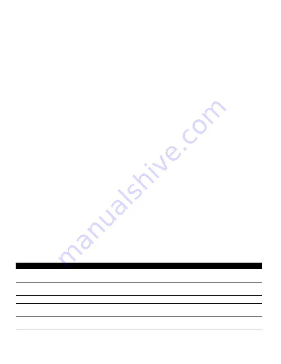
Symptom

Problem

Action

System non-operational

Main breaker tripped

Reset main breaker

Pressure switch contacts corroded

Replace switch

Compressor motor not running

Main breaker tripped

Reset main breaker

Thermal overload tripped

Allow several minutes to cool and  restart

No duplex outlet power

Circuit breaker tripped

Reset duplex breaker

Tank pressure exceeds 110 psi.

Pressure switch settings altered

Readjust according to Pressure Switch 
Replacement section note

Compressor attempts to restart under load

Leaking or obstructed check valve

Disassembly and clean or replace.

Misaligned unloader valve

Tighten unloader valve screw and realign.

Extended compressor cycle time

Air demand has been altered

Readjust instruments

Clogged intake filters.

Clean or replace.

Air line leaks.

Tighten couplings, retape.

Water collected in air storage tank.

Blow off tank

Summary of Contents for AA-75CF

Page 1: ...ANUAL PARTS LIST AA 75CF NSN 6520 01 456 7170 Part 2 of 2 P O Box 1548 Woodinville WA 98072 1548 1 800 426 5913 425 487 3157 Fax 425 487 2608 email info aseptico com Internet www aseptico com 12 98 P...

Page 2: ...Compressor 18 Intake Fan 20 Aftercooler 20 Motor Exhaust 22 Electronics Module 22 Pressure Switch 22 Top Cover 24 Expendables 26 Table of Illustrations Figure A AA 75CF Component Identification 5 Fig...

Page 3: ...m ference of the joint A leak at a seal will cause the solution to bubble Tighten the joint if necessary reapply Teflon tape until bubbles no longer appear Inspection The felt media of the air intake...

Page 4: ...ank pressure than is common Check system tubing and fittings for leaks Inspect compressor air intake filters Replace filter cartridge if required No power to duplex outlet Verify system is powered Res...

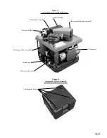
Page 5: ...Pressure Switch Air Storage Tank Assembly Transformer Electronics Module Compressor Aftercooler Housing Assembly Exhaust Baffle Figure A AA 75CF Component Identification Figure B Compressor Chassis R...

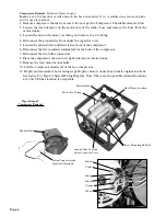
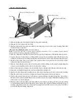
Page 6: ...e compressor 6 Disconnect the five insulated terminals from the back of the compressor 7 Disconnect the two inline connectors 8 Place the compressor chassis on its right side motor intake down 9 Remov...

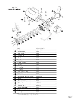
Page 7: ...720015 Piston Ring 730383 Piston Seal 730383 Piston Rod Assembly 720015 Rider Ring 730383 Motor Mount Bolt Nut Washer Commercial Motor 720015 Motor Tee Fitting 730358 Motor Intake 460784 08 Crossover...

Page 8: ...ed solvents to clean valves or any liquids to flush units The stainless steel valves may be cleaned with water All parts except the valves can be cleaned with any industrial non flammable non toxic no...

Page 9: ...ank by depressing the release ring and pulling on the tube Note the tube routing 5 Rotate the compressor chassis onto its left side motor exhaust side Depress the release ring on the push in straight...

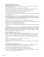
Page 10: ...e to seal pipe threaded fittings Note In addition to exposing wire connections removing the pressure switch cover exposes a pair of adjustment screws used to control the AA 75 CF compressor s cut off...

Page 11: ...8 1 in Unloader tube 10 0 in Case side tank drain tube 15 0 in Tank side tank drain tube 24 0 in Case drain tube 15 5 in 4 Slide the fitting nut and the appropriate new ferrule onto the tube and re at...

Page 12: ...top cover 8 Remove the fan motor being careful not to bend the impeller 9 Replace intake fan and reattach by reversing steps Install fasteners using a serviceable thread locking compound Strip wires...

Page 13: ...Page 13 AA 75CF SYSTEM WIRING SCHEMATIC AA 75CF SYSTEM PNEUMATIC SCHEMATIC Figure J Figure K...

Page 14: ...2 3 4 5 PARTS LIST ITEM PART NUMBER QUANTITY Case Mil Spec Top 410128 1 Case Leg 460776 08 2 Case Leg Pivot 460802 08 4 Case Leg Bumper 460828 4 NUT Nylok Stnl 10 32 Commercial 4 230V Power cord 84000...

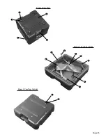
Page 15: ...Page 15 1 2 3 4 5 2 3 5 8 6 7 4 1 Figure 1 Case Base Figure 2 Case Top Inside 9 10 Figure 3 Case Top Outside...

Page 16: ...hassis Cover Channel Back 460789 08 1 Chassis Cover Channel Right 460770 08 1 SCREW Button head socket Commercial 24 Stnl 10 32 x 3 8 SCREW Button head socket Commercial 16 8 32 x 3 8 WASHER int star...

Page 17: ...Page 17 1 2 3 4 5 6 7 8 9 10 11 12 13 14 15 17 16 18 Figure 4 Compressor Chassis 1 2 3 4 5 6 Figure 5 Air Storage Tank...

Page 18: ...ce Figure 7 ITEM PART NUMBER QUANTITY Compressor 720015 1 Motor Intake 460784 08 1 Crossover Tube 460777 08 1 FITTING A B branch tee 730358 1 1 2 tube x 1 4 MPT FITTING A B Male Elbow 730357 1 3 8 tub...

Page 19: ...Page 19 1 2 7 3 4 6 5 Figure 6 Transformer 1 2 3 4 5 6 7 8 9 10 11 12 Figure 7 Compressor 13...

Page 20: ...ER QUANTITY Aftercooler Housing 460749 08 1 SCREW Button head socket Commercial 5 Stnl 10 32 x 3 8 Aftercooler Fan 330264 1 Aftercooler Fan Filter Assembly 730333 1 BOLT Flat head Phillips Stnl Commer...

Page 21: ...Page 21 1 2 3 4 5 6 7 8 9 10 Figure 8 Intake Fan Figure 9 Aftercooler 1 2 13 3 4 5 6 7 8 9 10 11 12 11...

Page 22: ...head socket Commercial 2 Stnl 10 32 x 3 8 WASHER 6 Star Stnl 510419 1 NUT Nylok Stnl 6 32 Commercial 1 WASHER int star 10 stnl Commercial 2 1 2 3 4 5 Reference Figure 10 Reference Figure 11 ITEM PART...

Page 23: ...Page 23 1 2 3 4 5 6 7 8 Figure 10 Motor Exhaust Duct 1 2 5 Figure 11 Electronics Module Figure 12 Pressure Switch 1 2 3 4 5 6 7 3 4...

Page 24: ...er Connection Chassis 460798 08 1 SCREW Flat head Phillips Commercial 2 Stnl 6 32 x 3 8 SCREW Button head socket Commercial 2 Stnl 10 32 x 3 8 Leg Socket 460820 08 4 SCREW Flat head Phillips Commercia...

Page 25: ...Page 25 1 2 3 4 5 6 7 8 9 10 11 12 13 14 15 16 24 22 23 14 25 28 9 21 18 17 21 30 20 19 31 32 33 15 Figure 13A Top Cover Figure 13B Top Cover 33 34...

Page 26: ...Page 26 ITEM PART NUMBER Felt Filter Media 730382 Compressor Rebuild Kit 730383 Aftercooler Fan Filter Media 730380 Intake Fan Filter Media 730381 1 2 3 4 Expendables...

Page 27: ...Page 27 Notes...

Page 28: ...Box 1548 Woodinville WA 98072 1548 1 800 426 5913 425 487 3157 Fax 425 487 2608 email info aseptico com Internet www aseptico com Printed In The USA For Further Service And Or Technical Assistance Con...

Reviews: