Page 4
Motor won’t start with gauge pressure at 0 psi
The thermal protection of the compressor may have been activated. If system fans are still
functioning, allow the unit to cool briefly and restart. If system fans are not running, a high amperage
condition existed resulting in the system circuit breaker being tripped. This condition will result from
a leaking check valve or malfunctioning unloader valve.
Motor experiences labored start with gauge pressure below 70 psi
This condition results from the motor attempting to restart with pressure in the cylinder. This is an
indication of a leaking check valve or malfunctioning unloader valve. Inspect the check valve and the
unloader switch. Service components as required.
Motor starts at an intermediate pressure or Pressure relief valve is activated
Disconnect the unit from the power source. Inspect the pressure switch for excessive wear and
damaged or dirty components. Replace parts as required.
Compressor cycles more frequently than is common
Shut off compressor. Watch the tank pressure gauge. If the tank pressure drops rapidly, check tubing
and fittings for leaks. If tubing and fittings are satisfactorily connected, the check valve should be
inspected for dirt and damage. If after shut off tank pressure is maintained, the tank should be blown
off. Water vapor can condense in the tank and reduce its capacity.
Compressor takes longer to build tank pressure than is common
Check system tubing and fittings for leaks. Inspect compressor air intake filters. Replace filter
cartridge if required.
No power to duplex outlet
Verify system is powered. Reset duplex outlet circuit breaker.
Disassembly, Repair, Replacement, Reassembly and Check Out
The AA-75CF has been designed for minimal required maintenance. Compressor service should be
performed every two thousand hours and component service should be required only when compo-
nent damage occurs or service life is exceeded. Modular construction makes component inspection
and replacement simple. Maintenance can be performed with only the following tools: a 7/16 socket
drive, a set of English Hex wrenches, a 12 in. and an 8 in. crescent wrench, flathead and
#2 Phillips screwdrivers, and a 1/4 inch open face wrench.
For Reassembly, Teflon tape or an equivalent thread sealant should be applied to all pneumatics
fittings and a serviceable thread locking compound should be applied to all fasteners.
To check the success of any repair, perform the procedure detailed in the Performance Verification
section.
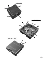
The first step in any major component replacement is the removal of the compressor chassis from
the case bottom.
Compressor Chassis Removal
Tools:
7/16 in. socket wrench and serviceable thread locking compound.
1. Remove case top.
2. Carefully place unit top cover down.
3. Remove the case bumper screws, sealing washers and case bumpers.
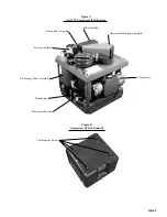
Reference Figure B
4. Lift off case bottom. Use a rocking motion to clear ID plate rivets.
5. Replace by reversing steps. Secure case bumper screws using thread locking compound.


