Page 6
Compressor Removal
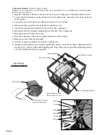
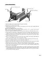
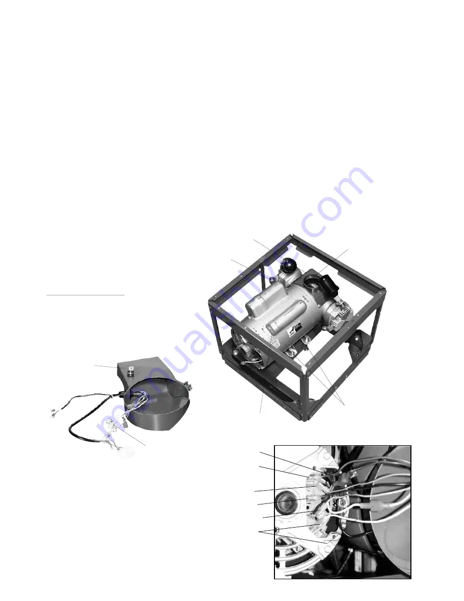
Reference Figure Group C
Tools:
1/4 and 5/16 hex drive or Allen wrench, flat head screwdriver, 12 in. or smaller crescent wrench, pliers,
and 1/4 open face wrench.
1. Remove compressor chassis from case bottom as per the Compressor Chassis Removal section.
2. Loosen the duct clamp at on the motor side of the intake hose and remove the hose from the
motor intake.
3. Loosen the nut on the motor tee fitting and remove the 1/2 tubing.
4. Disconnect the ground wire from under the capacitor cover.
5. Loosen the exhaust duct and twist it free from of the compressor.
6. Disconnect the five insulated terminals from the back of the compressor.
7. Disconnect the two inline connectors.
8. Place the compressor chassis on its right side (motor intake down).
9. Remove the four motor mount bolts.
10. Lift the compressor chassis off of the free compressor.
11. Repair and reassemble by reversing steps. Replace motor connections in their original locations.
See figure C or Figure I System Wiring Diagram. Note: There are two possible terminal locations
at 1 and 5. Either location is acceptable.
Motor Tee Fitting
Duct Clamp Location
Motor Intake
Motor Mounting Bolts (4)
Inline Connectors and
Insulated Terminals
Exhaust Duct
Ground Wire Location
Under Capacitor Cover
Brown
Violet
White
Orange
Black
Blue
Figure Group C
Compressor Removal


