Page 8
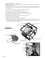
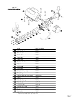
Compressor Motor Service Kit Installation
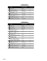
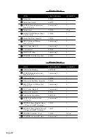
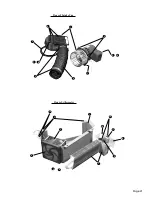
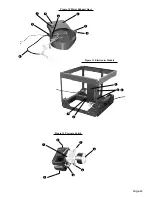
Reference Figure D
(Adapted from Gast Operation & Maintenance Technical Manual).
The compressor motor service kit contains the following: Head Gasket, Valves, Cylinder gasket,
Piston Rings, Piston Seals, Rider Ring, and Felts.
Dis-Assembly
Tools:
3/16, 1/4, and 5/16 hex drive or Allen wrench, flat head screwdriver, 12 in. or smaller crescent wrench,
pliers, and 1/4 open face wrench.
1. Disconnect the compressor from the electrical power.
! CAUTION !
You must disconnect the pump from electrical power before servicing it. Failure to do
so can result in severe personal injury or death.
2. Drain the air storage tank and turn the pressure switch to the OFF position.
! CAUTION !
You must vent all air lines to the compressor to remove pressure before servicing.
Failure to do so can result in severe personal injury.
3. Remove the unit from the case bottom and the compressor from the compressor chassis as
described in the Compressor Chassis removal and Compressor Removal subsections above .
4. Remove the motor intake and the crossover tube from the compressor.
5. Remove the cylinder heads, and valve components. DO NOT re-arrange or reorient the valve
components.
6. Remove the cylinder and rings.
Make sure all compressor parts are clean before reassembling.
DO NOT
use any chlorinated
solvents to clean valves, or any liquids to flush units. The stainless steel valves may be cleaned with
water. All parts, except the valves, can be cleaned with any industrial, non-flammable, non-toxic,
non-petroleum based cleaning solvent.
Assembly
1. Install piston seals, piston rings, and rider ring on each piston.
2. Locate ring joints approximately opposite each other.
3. Finger tighten the cylinders to the bracket with the cylinder screws and washers.
4. With the piston in its top dead center position, adjust each cylinder flush with top of piston and
torque cylinder screws to 150-160 inch lbs. Re-torque second time.
5. Stack the valve components in order as originally assembled.
6. Install the cylinder head and head screws.
NOTE:
The exhaust ports in the cylinder heads have been marked by omitting the ends of two of the
fins.
7. Torque all head screws 150-160 inch lbs.
8. Turn the motor shaft by hand at this point to ensure that the rod assembly is not hitting the head.
NOTE:
If rod assembly does hit head, loosen cylinders and re-adjust.
9. Replace the motor intake and crossover tube.
10. Re-torque head screws again after running for 10 minutes.
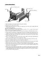
Replacing Aftercooler Housing Parts
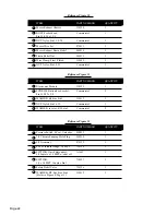
Reference Figure E
Aftercooler Fan Replacement
Tools:
1/8 hex drive or Allen wrench, #2 Phillips screwdriver, 12 in. or smaller crescent wrench, and thread
locking compound.
1. With compressor chassis extracted remove the five aftercooler housing bolts from the top cover.
2. Lift aftercooler housing and disconnect the fan plug.


