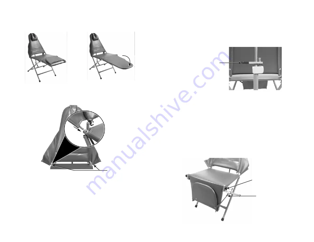
4. Insert right and left arm sling pins into holes on the sides of the seat frame.
(Fig. 4)
5. Complete set-up by positioning backrest and placing headrest at the proper
height on the front side of backrest.
CHAIR
ADJUSTMENTS:
1.
Seat
Height-
The ADC-01CS chair seat height can be set at any of the five
preset settings. Without a patient in the chair, put your toe on one of the front
chair legs and lift up slightly on the chair seat. While lifting seat, remove the leg
adjustment pin from the right and left side. Align link with tube hole in any of the
five positions and lock in place by inserting chain and pin. (see Fig. 1)
2.
Backrest-
The backrest may be set in any position from upright to full supine.
To change the position of the backrest, simply lift the chrome friction lever on the
back side of the backrest, lower backrest, then release lever to lock.
NEVER
LOWER
THE
BACKREST
WHEN
A
PATIENT
IS
IN
THE
CHAIR
WITHOUT
COMPLETELY
SUPPORTING
THEIR
WEIGHT
FIRST.
To return the backrest to
an upright position, lift backrest to desired position. Backrest will automatically
lock in place. (Fig. 5)
3.
Footrest-
The footrest may be positioned in the normal horizontal operating
position, or allowed to hang down vertically so a patient can be seated in a sitting
position. To release footrest into the vertical position, first fold toe section inward,
then lift slightly on footrest section. While lifting, pull the black knobs on each
side of the chair frame to release and push footrest down into the vertical
positon. Lock in the vertical position by snapping holding strap around the chair
leg frame.
To reposition footrest in the horizontal position, unsnap holding strap from frame,
lift footrest to the horizontal position until it locks, then unfold toe section out to
horizontal. (Fig. 6)
Pull black knob to release
Snap around frame
Fig. 6
4.
Headrest-
The headrest slides freely on its mounting strap and can be
positioned at different heights for different size patients.
Insert pins into frame holes
3. When the chair has been raised and the height set, the foot and leg
portion should be folded forward, out horizontally. It will stop in the
horizontal p o s i t i o n . ( F i g . 3 )
Fig. 3
Fig. 4
Lift lever to position.
Release to lock.
Fig. 5


