10
ADC-02CF
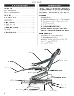
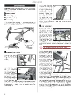
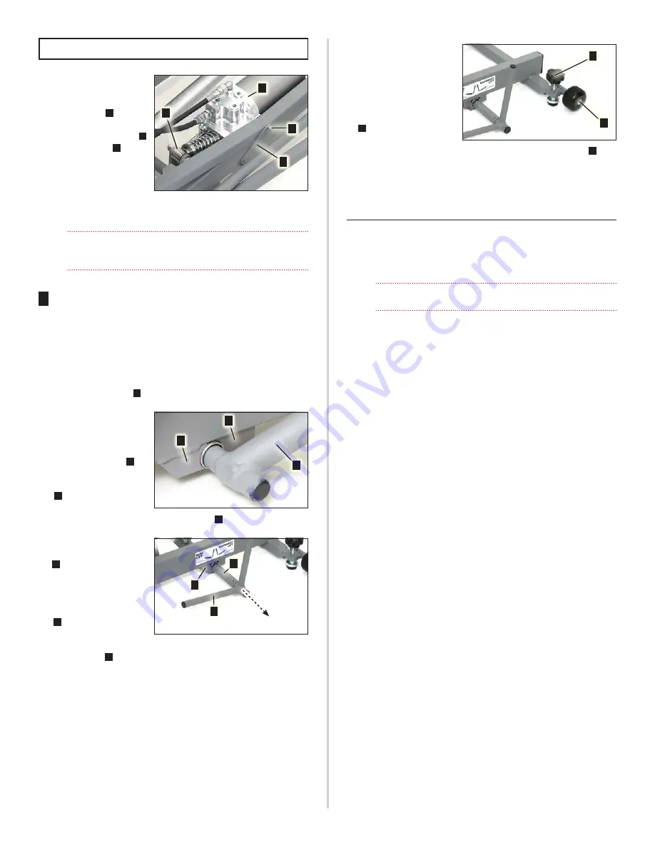
Use a 3/16’’ Allen wrench
to remove the bolts [2x PN
510692] and washers [2x PN
510500] (Fig. 21
A
) that at‑
tach the pump mount stiff‑
ener [PN 462259] (Fig. 21
B
)
and pump (Fig. 21
C
) to the
base frame. Remove the
hydraulic pump, two cyl‑
inders and two hoses that
comprise the entire hy‑
draulic assembly without disconnecting any hydraulic components
nor opening any hydraulic ports.
Disassembly of the hydraulic assembly is not recommended
unless a component malfunctions. Refer to the
Schematic
Drawings
(page 14) for configuration details.
4
BASE ASSEMBLY
Disassembly of the ADC‑02CF base is not necessary unless a com‑
ponent breaks. If disassembly is required, remove the primary com‑
ponents as follows:
Use a 5/16’’ Allen wrench and 9/16’’ combination wrench to remove
the bolt [PN 510812], roller [PN 462233], bushing [PN 520105] and
nut [PN 510811] (Fig. 21
D
) from the lift lever.
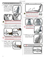
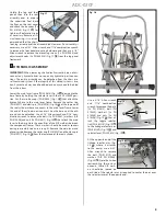
Use a 3/16’’ Allen wrench
to remove the bolts [4x PN
510813] that attach the le‑
ver mounting brackets [2x
PN 462243] (Fig. 22
A
) to
the base frame. When re‑
moving the lift lever (Fig.
22
B
), note the bearing
pins [PN 510818] mounted
inside each of the mating brackets (Fig. 22
C
).
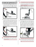
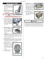
Remove the selector ped‑
als [2x PN 330636] (Fig.
23
A
) on each side of the
chair by depressing the
locking buttons and pull‑
ing the selector pedals out
of selector lever bar (Fig.
23
B
). Use a 3/16’’ Allen
wrench to remove the
bolts [4x PN 510813] that attach the pump switch brackets [2x PN
462242] (Fig. 23
C
) to the base frame. Use a 3/32” Allen wrench to
remove the bearing screws [2x PN 510857]. Remove the selector
lever bar [PN 330625] with bearings [2x PN 462511].
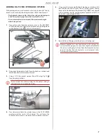
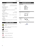
Use two 1/2” combination
wrenches to remove the
bolts [2x PN 510806], bear‑
ings [4x PN 520115], spacers
[2x PN 510823] and nuts [2x
PN 510126] that attach the
wheels [2x PN 730679] (Fig.
24
A
) to their struts.
The knob [PN 850042] and leveling foot [PN 850044] (Fig. 24
B
) and
the rubber feet [2x PN 462312 & 1x PN 462390] do not require disas‑
sembly or maintenance and can be left attached to the frame.
THIS COMPLETES THE DISASSEMBLY PROCEDURE FOR THE
CHAIR
REASSEMBLY:
To reassemble the chair, follow the above instructions in the re‑
verse order.
Refer to the
Schematic Drawings
(page 14) for part numbers
and configuration drawings when reassembling chair.
Fig. 21
Fig. 21
B
D
A
C
Fig. 22
Fig. 22
A
C
B
Fig. 23
Fig. 23
A
C
B
Fig. 24
Fig. 24
A
B
DISASSEMBLY
(Continued)
Summary of Contents for ADC-02CF
Page 14: ...14 ADC 02CF ...
Page 15: ...15 ADC 02CF ...


