8
ADC-02CF
DISASSEMBLY
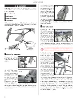
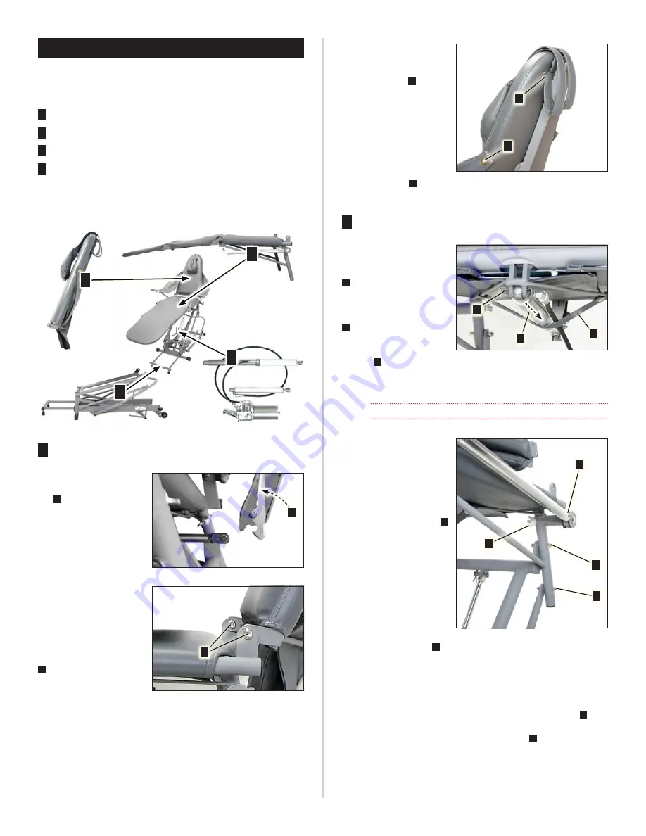
OVERVIEW
: When disassembling the ADC‑02CF Chair, it is recom‑
mended that its modular components be detached and removed
in the following order:
1
Backrest Assembly
2
Seat Assembly
3
Hydraulic Assembly (*)
4
Base Assembly
(*) The individual components of the hydraulic assembly are not
customer‑serviceable and shouldn’t be disassembled in the field.
Return to Aseptico if repairs are required.
1
2
3
4
1
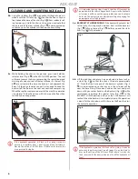
BACKREST ASSEMBLY
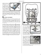
Disengage the backrest
latch [PN 462239] (Fig.
12
A
) from the backrest
cylinder.
Use a 3/16” Allen wrench
and 1/2” combination
wrench to remove the bolts
[2x PN 510815], washers [4x
PN 510845], spacer wash‑
ers, [A/R PN 510297] and
nuts [2x PN 510126] (Fig. 13
A
) that attach the backrest
assembly to the seat frame.
Note the quantities and po‑
sitions of the “A/R” (as required) spacer washers between the com‑
ponent frames. These washers should be used as spacers during re‑
assembly to ensure a snug fit. Detach the backrest assembly and
set on workbench.
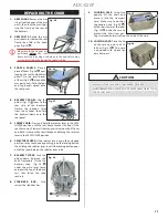
Use a Phillips screwdriver
to remove the pillow strap
mounting screws [2x PN
510239] (Fig. 14
A
) that at‑
tach the pillow strap [PN
462313] to the rear of the
backrest. Remove strap
and pillow [PN 462304].
Use a 5/32” Allen wrench
to remove the screws
[PN 510841], washers [PN
510500] and bushings [PN
462301] (Fig. 14
B
) that attach the arm slings [PN 462289] to the
sides of the backrest.
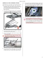
2
SEAT ASSEMBLY
Remove the clevis pin
[PN 510917] and cotter
ring [PN 510927] (Fig. 15
A
) that attach the back‑
rest cylinder to the under‑
side of the seat assembly.
Push the cylinder (Fig. 15
B
) with attached hydrau‑
lic hose backward over the
support strap [PN 462291]
(Fig. 15
C
) and out from under the seat. Rest the cylinder on the
floor until the complete hydraulic system can be detached as a
unit.
Do not disconnect the hydraulic hose from the cylinder.
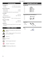
Fold the foot and leg pan‑
els closed onto the seat
panel. Use a 3/16” Allen
wrench and 7/16” combina‑
tion wrench to remove the
bolts [2x PN 510842], wash‑
ers [6x PN 510500] and nuts
[2x PN 510296] (Fig. 16
A
)
that attach the seat frame
to the base struts [2x PN
462191]. Note: One wash‑
er is installed between the
seat frame and each strut.
Use a 1/4” Allen wrench and
1/2” combination wrench
to remove the bolts [2x PN
510809], spacer washers [8x
(A/R) PN 510845] and nuts
[2x PN 510126] (Fig. 16
B
) that attach the seat frame to the main le‑
ver [PN 330614]. Note the quantities and positions of the A/R spacer
washers between the component frames; these washers should be
used as spacers during reassembly to ensure a snug fit. Detach the
seat assembly and set on workbench. Remove the wing nuts [2x PN
510311], bolts [2x PN 510810], rubber washers [4x PN 710138], coved
washers [2x PN 510822] and washers [2x PN 510845] (Fig. 16
C
) that
attach the arm posts to the seat frame. Use an 1/8’’ Allen wrench
to remove the small screws [6x 510312] (Fig. 16
D
) that connect the
arm post components together.
A
Fig. 12
Fig. 12
Fig. 13
Fig. 13
A
Fig. 14
Fig. 14
A
B
Fig. 15
Fig. 15
B
A
C
Fig. 16
Fig. 16
A
B
C
D
Summary of Contents for ADC-02CF
Page 14: ...14 ADC 02CF ...
Page 15: ...15 ADC 02CF ...


