9
ADC-02CF
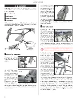
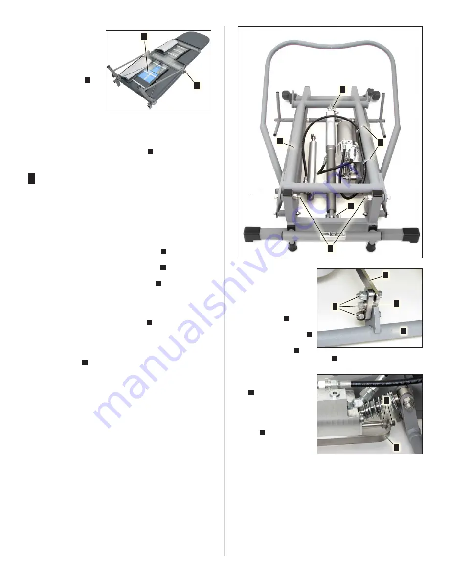
Unfold the leg and foot
panels then turn the seat
assembly over to expose
the underside. Peel back
the flaps on the seat cover
and check the tie wraps [9x
PN 510135] (Fig. 17
A
) for
tightness. Replace tie wraps
as necessary. Because of its
vinyl covering, it is not rec‑
ommended that the chair’s
foot, leg, or seat panels be disassembled. However, if disassembly is
necessary, use a 5/32’’ Allen wrench and 7/16’’ combination wrench
to remove the foot panel mounting hardware and then use a 1/4’’
Allen wrench to remove the mounting screws [2 x PN 510048] and
adjustment knobs [2x PN 850025] (Fig. 17
B
) from the leg panel
framework.
3
HYDRAULIC ASSEMBLY
IMPORTANT:
When removing the hydraulic assembly, do not dis‑
connect any hydraulic lines nor open any hydraulic port connec‑
tions. The entire assembly can be detached from the chair as a
self‑contained system. If the integrity of this closed system is bro‑
ken, hydraulic oil may need to added and air may need to be bled
from the system.
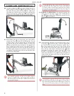
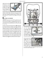
Lower the main lever frame [PN 330614] (Fig. 18
A
) down onto the
base frame by holding the selector lever in the SEAT LOWER posi‑
tion. Cut the two tie wraps [PN 510835] (Fig. 18
B
) that attach the
hydraulic hose to the main lever frame. Remove the cotter ring
[PN 510927] and clevis pin [PN 510916] (Fig. 18
C
) at the top end of
the seat cylinder where it connects to the main lever frame. Lower
this end of the cylinder down and rest it on the base until the oth‑
er end can be detached. Use a 5/16’’ Allen wrench and 9/16’’ com‑
bination wrench to remove the bolts [2x PN 510847], washers [A/R
PN 510846] and nuts [2x PN 510811] (Fig. 18
D
) that attach the main
lever to the base. Note the quantities of the A/R washers between
the component frames. These washers should be used as spacers
during reassembly to assure a snug fit. Remove the main lever and
place it aside. Remove the cotter ring [PN 510927] and the clevis pin
[PN 510917] (Fig. 18
E
) from the lower end of the seat cylinder.
Fig. 18
Fig. 18
A
B
C
D
E
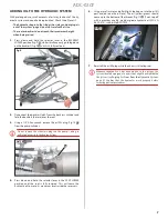
Use a 3/16’’ Allen wrench
and 7/16” combination
wrench to remove the bolts
[2x PN 510813], bolt [PN
510339], washers [2x PN
510500] and nuts [2x PN
510296] (Fig. 19
A
) that at‑
tach the toggle selector
link [PN 462218] (Fig. 19
B
)
to the linkage selector arm
[PN 462249] (Fig. 19
C
) and
selector lever [PN 330625] (Fig. 19
D
).
At the opposite end of the
linkage selector arm (Fig.
20
A
), where it attaches
to the pump, use a 5/32’’
Allen wrench to remove
the bolt [PN 510119] and
washers [A/R PN 510500]
(Fig. 20
B
). Note that when
reassembling these com‑
ponents, these A/R wash‑
ers should be spaced on
each side of the selector arm as required to center the arm over
the selector lever at the opposite end.
Fig. 17
Fig. 17
A
B
Fig. 19
Fig. 19
B
C
D
A
Fig. 20
Fig. 20
B
A
Summary of Contents for ADC-02CF
Page 14: ...14 ADC 02CF ...
Page 15: ...15 ADC 02CF ...


