background image

6.

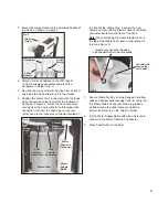
b.) Release pressure from Bottle by slightly

loosening bottle from reservoir connector

approximately 1/8-turn, or by depressing the

air button on the 3-Way Syringe. 

c.) Unscrew and remove Bottle from cap.

d.) Fill Bottle with clean water.

e.) Screw Bottle into the Water Reservoir

Connector.

f.) Plug in the power cord.

6. HVE and SALIVA EJECTOR VACUUMS:

The Express II is equipped with a 5-liter Waste

Tank, a High Volume (HVE) hose, and a Low

Volume (Saliva Ejector) hose. Both High and

Low Volume systems operate simultaneously

from the same vacuum source. To gain vacuum

on the HVE, open the HVE valve to full open and

close the Saliva Ejector Valve. To gain vacuum

on the Saliva Ejector, close the HVE and open

the Saliva Ejector to full open.
The vacuum Waste Tank contains a ball float

shutoff to prevent accidental overflow. The Tank

should be emptied when it is ¾ full.
The High Volume (HVE) vacuum system

contains a screen inside the Waste Tank

container. The screen is used for collecting large

debris upon vacuum intake. Clean screen when

necessary.

To empty the Waste Container:

a.) Unplug the power cord.

b.) Disconnect the hoses.

c.) Empty container.

d.) Reconnect hoses.

e.) Plug in power cord.

7. CAVITRON WATER OUTLET:

Provides water via standard 1/4” quick

disconnect to independent Cavitron or scaler

units requiring a water supply.

The waste container has a ball float shutoff to

prevent accidental overflow. If the waste container

becomes full and the ball float activates, the

vacuum motor may not restart, and could

potentially blow the fuse. Immediately empty

waste container to continue operation.

NOTE:

OPERATION FUNCTIONS:

1. FOOT SWITCH RUN MODE:

All Express II System components are activated

by the on/off Foot Switch. The Foot Switch

enables the operation of the handpiece, high

vacuum, Saliva Ejector, and the 3-Way

Air/Water Syringe.

2. CONTINUOUS RUN MODE:

Enables all the Express II System components

to operate in continuous mode without

activating the foot switch.

3. HANDPIECE CONTROLS:

a.) Handpiece Off/On Toggle Switch - Turns

Handpiece pneumatic drive pressure Off/On.

b.) Off/On Coolant Toggle Switch - Turns

Handpiece water coolant On/Off.

c.) Air Control Switch - Allows adjustment of air

pressure to the Handpiece.

d.) Coolant Control Switch - Allows adjustment

of water coolant to the Handpiece.

4. THREE-WAY AIR/WATER SYRINGE:

- Pressing the left button dispenses water.

- Pressing the right button dispenses air.

- Pressing both buttons simultaneously

dispenses an air/water mist.

5. WATER SUPPLY BOTTLE:

The Express II incorporates a self contained

pressurized water system. This system consists

of a 1-liter white bottle, which dispenses water

through the handpiece and 3-Way Air/Water

Syringe. The Water Supply Bottle threads into

the Reservoir Connector, located in the upper

right corner of the case.

To refill the Water Supply Bottle:

a.) Before removing the Bottle for refilling,

unplug the power cord from the Express II

unit.

THE WATER SUPPLY BOTTLE IS

PRESSURIZED DURING OPERATION.

DEPRESSURIZE BOTTLE BEFORE

REMOVAL BY SLIGHTLY LOOSENING

BOTTLE FROM RESERVOIR

CONNECTOR.

WARNING:

Summary of Contents for ADU-17X Express II

Page 1: ...ADU 17X Express II Portable Dental System OPERATION and MAINTENANCE INSTRUCTION MANUAL...

Page 2: ...to property please heed relevant warnings and remarks They are marked as follows WARNING Serious injury or death may result if ignored CAUTION Damage to property or the environment may result if ignor...

Page 3: ...provide many years of reliable service Please read the instructions provided in this manual to receive the best and longest service from your Aseptico equipment Separate manuals may be provided to cov...

Page 4: ...g WARNING Use for intended purposes only Failure to observe the operating instructions may result in the patient or user suffering serious injury or the the product being damaged possibly beyond repai...

Page 5: ...HVE VOLTAGE SELECTOR MODULE WASTE TANK WASTE TANK TIE DOWN WATER SUPPLY BOTTLE LOW VOLUME VACUUM SALIVA EJECTOR FOOT SWITCH RUN MODE SWITCH CASE HANDLE RESERVOIR CONNECTOR COMPRESSOR AND FAN HOUSING...

Page 6: ...ing releases Figure 2b Carefully remove fuse housing to reveal Voltage Selector Insert Figure 2c Pull insert out of housing turn it around and reinsert into housing with proper voltage indicator facin...

Page 7: ...Ejector hose to the black connector located on the front of the Tank Note When attaching the Saliva Ejector hose to the top of the Waste Tank push in and rotate 1 4 turn see Figure 5 7 Secure Waste T...

Page 8: ...nd the ball float activates the vacuum motor may not restart and could potentially blow the fuse Immediately empty waste container to continue operation NOTE OPERATION FUNCTIONS 1 FOOT SWITCH RUN MODE...

Page 9: ...ng 6 Adjust the vacuum pressure by moving the valves on both the HVE and saliva ejector vacuum heads 7 Empty the Vacuum Waste Tank when it is 3 4 full After you have set up the Express II unit and hav...

Page 10: ...for 10 minutes Remove water supply tank and discard bleach Flush water supply tank and all lines thoroughly with clean water Air purge and leave lines dry until next clinical use VACUUM SYSTEM The HV...

Page 11: ...operation Check vacuum hose assembly for blockage Check that waste container lid is properly seated and tightly secured Check that handpiece ON OFF toggle is ON Check that handpiece coolant ON OFF tog...

Page 12: ...ce travel pouch with water bottle on top of coiled hoses 6 Coil foot switch cable and place in pouch with foot switch Coil motor drive air line and place in pouch Place power cord and fuses in pouch C...

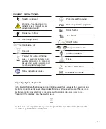
Page 13: ...pment must not be disposed as unsorted municipal waste and must be collected separately Disposing of your old product Each Member State in the European Union EU requires that the waste from electrical...

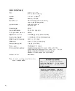
Page 14: ...o 60 C 4 to 140 F Relative Humidity 10 to 90 non condensing Altitude 0 to 3048 meters 0 to 10 000 feet Unit Duty Cycle Continuous This device has been tested and found to comply with the emissions req...

Page 15: ...ter of such action In the event of alleged defect under warranty the purchaser is to notify Aseptico s Customer Service Department promptly Customer Service will provide instructions usually directing...

Page 16: ...P N 420627 Rev L ECO 14117 03 2017 PRINTED IN THE U S A P O Box 1548 Woodinville WA 98072 8333 216th Street SE Woodinville WA 98072 425 487 3157 800 426 5913 www aseptico com info aseptico com...

Reviews: