6
AEU-1070-70V / AEU-1070
7 .
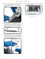
Place the motor-handpiece onto the cradle
A
.
A
8 .
Pull the lever
A
on top of the console to release the pump
door, then pull the pump door
B
fully open.
B
A
9 .
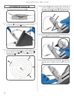
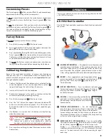
While installing the irrigation tubing it will be helpful to be
able to identify the bayonet
A
, large tubing connector
B
,
peristaltic tube segment
C
, Luer connector
D
, and the small
tubing connector
E
.
A
C
D
E
B
10 .
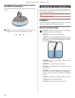
Two red arrows
A
on the pump door show the direction to
install the irrigation tubing. Start by threading the peristaltic
tube segment through the top slot
B
in the pump door. The
large tubing connector
C
should be above the slot, as shown.
A
B
C
11 .
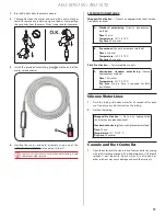
Pull the tube down through the top slot until the large tubing
connector
A
seats securely into the slot.
A
12 .
Following the next red arrow on the door, thread the peri-
staltic tube segment through the bottom slot
A
on the pump
door.
A
SYSTEM SETUP (Continued)


