To check the functions of the dental motor and unit, attach
motor and foot pedal as described in the Operations Manual.
Push the buttons marked “Fiber Optic Light” and “Water” so
that the LEDs are on. Depress the foot pedal and ensure that
handpiece light comes on (you might have to depress the
po] button until light is present) and that water
comes out of the handpiece. Adjust the water flow with the
coolant adjustment knob on the unit. If light fails to come on,
first check the bulb in the motor. If bulb is okay, then work
your way back through the connectors. If water fails to come
out of the handpiece, check the two-way valve. If the motor
fails to operate, check the connector pins on the motor and
the foot pedal. If the motor fails to operate from the foot
pedal, then activate the button marked “Manual”. If the
motor comes on, the problem is in the foot pedal. Check
reverse mode by pressing the “Reverse” button, and check
the motor speed by pressing the po] and negative[-]
buttons.
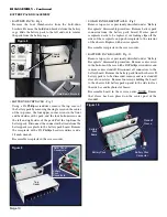
Remove the AC power cable and attach the vehicle battery
cable to the chassis and either a 12V or 24V battery system.
Follow the setup procedure in the Operation Manual. Turn
the battery on/off switch on and the unit should light up. If
the unit fails to light up, remove the chassis as described later
in this manual (refer to page 5) and check the 15 amp fuse
coming from the vehicle receptacle on the inside of the unit .
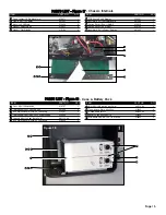
To check the operation from the battery packs, remove other
sources of power. Attach the battery pack cable from a
battery pack to the unit. Turn the battery on/off switch on and
the unit should light up and show the charge level of the
battery pack. If the unit fails to come on, check the
connections from the battery pack to the unit.
To check the operation of the charging system, leave the
battery pack hooked up to the unit and apply either
120V/220V or 12V/24V vehicle power to the unit. The unit
will take power from the higher source. If 120V/220V power
is applied, the power on/off switch must be turned on to
check the charging. If power is coming from 12V/24V battery,
then only the battery switch needs to be on. Press the
“Charge” button on the unit and ensure that the LED lights
up.
The above procedures describe basic inspection and
verification of the AEU-14CF system. If the unit still does
not perform as required, further diagnosis of components in
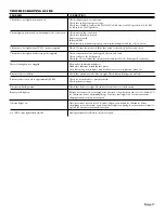
the system may require service. Use the Trouble Shooting
section as a guide to symptoms and appropriate procedures
to fix various problems.
GENERAL SERVICE INFORMATION
This service and parts manual offers information and parts
lists not available in the AEU-14CF Operation and
Maintenance Instruction Manual. It will help you better
understand the operation of the AEU-14CF Expedition
Emergency Field Dental Unit, thereby reducing service time.
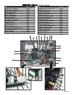
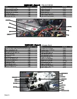
A Schematic Diagram Set includes part drawings and
schematic diagrams which show components in their actual
places in the unit relative to one another. A plumbing
schematic is provided with water lines indicated in blue.
Plumbing parts are called out by Aseptico part number in the
assembly drawings. Electrical schematics are provided for the
chassis and battery pack with wires color coded. Electrical
parts are called out by Aseptico part number in the assembly
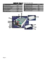
drawings. Parts are listed and referenced to Figures with
callouts in the Parts List. Use the information in the Parts
List when ordering replacement parts.
Inspection & Operation Verification
To verify that the AEU-14CF unit is functioning properly,
first follow the set-up procedure in the Operation &
Maintenance manual. The system is designed to run off of
multiple power systems, so it is best to isolate systems during
diagnostics. First, plug the system into a 120V/220V power
source. The system is auto switching but the fuses should be
changed for the appropriate voltage, which is listed on the
silkscreen above the receptacle. Turn the power On/Off
switch ‘On’ and the panel should light up and the compressor
pump should fill the air and water reservoirs. If the water
reservoir is empty, the pump will take longer to charge the
system. With the compressor pump engaged, the system
should pressurize to approximately 22 PSI, as indicated on
the pressure gauge. When the compressor pump is first
initialized, a three-way valve allows for the pump not to start
against a pressure head. If the unit fails to show any pressure
on the gauge, the three-way valve is usually at fault. Inspect
the unit for air and water leaks. If the pump fails to shut off
and the pressure gauge shows some pressure, then there is a
leak present. The electronics have been coated to prevent
shock. It is possible to detect air leaks with a tube or a
stethoscope, but because of the low pressure, they are hard to
detect in this manner. It is better to use the plumbing
schematic and isolate the problem by pinching off the lines
with clamps, such as a pair of hemostats. If an air leak is not
detected on the lines or fittings, check the bottles for
tightness and the condition of the seals. To check the three-
way syringe, depress the air and water buttons individually
and then both buttons together for spray. The spray will be
less than a normal dental system, due to the lower pressure of
the system. Inspect the water filter on the water pick-up tube.
The water filter requires replacement if it becomes clogged
and restricts water flow. The compressor pump has a 90 PPI
filter on the underside of the chassis that requires
replacement if it becomes clogged and restricts air flow.
Page 3

