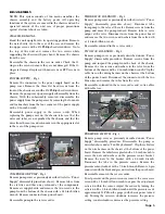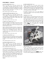
Page 6
DISASSEMBLY - Continued
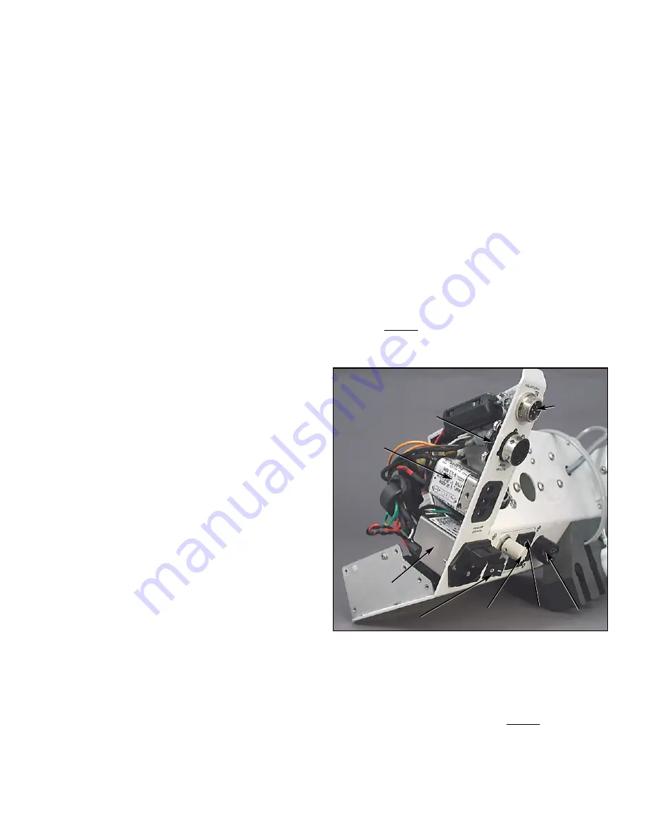
BATTERY RECEPTACLE - Fig. 3
Remove the pump cover as previously described under
“Power Supply” disassembly procedure. Remove the nuts
and washers with a 1/4-inch socket. Clip the wire ties on the
cables coming from the connector. Disconnect the terminals
from the battery on/off switch and unplug the 4-pin
connector from the power board.
Reassemble receptacle in the reverse order.
VEHICLE BATTERY RECEPTACLE - Fig. 3
Remove the pump cover as previously described under
“Power Supply” disassembly procedure. Remove the nuts
and washers with a 1/4-inch wrench. Clip the cable ties and
remove the terminals to the battery switch and the 2-pin
connector to the power board.
Reassemble receptacle in the reverse order.
POWER CORD RECEPTACLE - Fig. 3
Remove the pump cover and pump as previously described
under “Power Supply” and “Compressor Pump” disassembly
procedures. Clip the cable ties on the wire harness at the
bottom of the power board.
Remove all nuts on the ground stud with a 5/16-inch wrench.
(The ground wire from the receptacle is the bottom wire.)
Remove the two flat-head screws in the front of the
receptacle with a #2 Phillips screwdriver. Remove the
terminals from the power on/off switch and remove assembly
from the chassis.
Reassemble receptacle in the reverse order.
POWER ON/OFF SWITCH - Fig. 3
Remove the two flat head screws from the power receptacle
and pull the receptacle forward. Remove the terminals from
the power switch and push the switch to the front of the
chassis.
Reassemble switch in the reverse order.
BATTERY POWER SWITCH - Fig. 3
Remove the pump cover as previously described under
“Power Supply” disassembly procedure. Disconnect the
terminals going to the switch and push the switch forward.
Reassemble switch in the reverse order.
FOOT SWITCH RECEPTACLE - Fig. 3
Remove the two screws holding the power cord receptacle
and pull the receptacle forward. Push the power switch
forward. Remove the pump cover as previously described
under “Power Supply” disassembly procedure and loosen the
pump to gain access to the ground stud. Remove the top
ground nut and clip the wire ties on the cable harness.
Remove the switch with a 3/4-inch wrench.
Reassemble receptacle in the reverse order.
MOTOR RECEPTACLE - Fig. 3
Remove the pump cover as previously described under
“Power Supply” disassembly procedure. Remove the screws
holding the pump to gain access to the ground stud. Remove
the top nut on the ground stud. Disconnect the 8-pin
connector at the top of the power board. Remove the four
nuts and washers with a 1/4-inch socket.
Reassemble receptacle in the reverse order. NOTE: If
replacing old receptacle, remove ferrite block and reinstall
onto new receptacle.
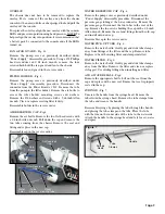
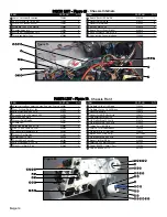
NEEDLE VALVE - Fig. 4
Remove pump cover as previously described under “Power
Supply” disassembly procedure. Remove screws from the
three-way and two-way valves. Remove the screws from the
filter holder and move out of the way to access the needle
valve. Remove the tubing from the needle valve. Remove the
knob from the front of the needle valve with a 1/16” Allen
wrench. Remove the needle valve with two 9/16-inch
wrenches. NOTE: It is recommended that a thin-walled
wrench be used on the inside nut.
Reassemble the needle valve in the reverse order.
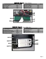
CHECK VALVE - Fig. 4
Remove the pump cover as previously described under
“Power Supply” disassembly procedure. Remove the screws
from the pump and swing the pump out of the way.
Disconnect the tubes to the check valve.
Reassemble valve in the reverse order. NOTE: the flow arrow
on the valve must be pointing toward the water bottle cap.
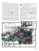
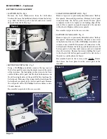
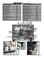
Figure 3
Battery
Receptacle
Footswitch
Receptable
Power Switch
Vehicle
Battery
Receptacle
Motor
Receptacle
Battery
Switch
Power Cord
Receptacle
Coolant
Adjustment

