Page 7
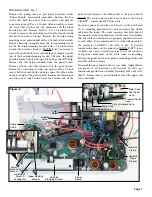
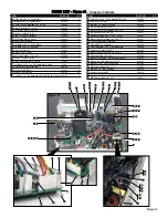
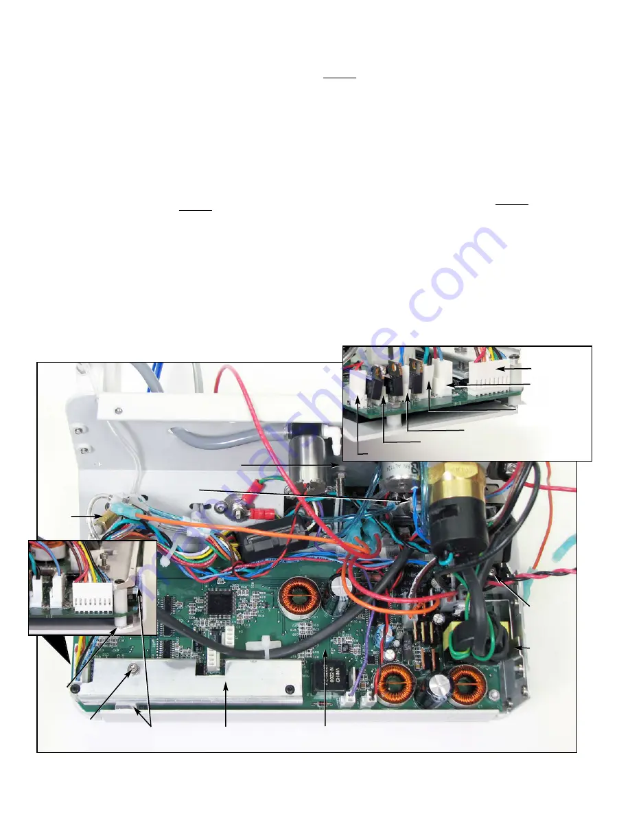
POWER BOARD - Fig. 4
Remove the pump cover as previously described under
“Power Supply” disassembly procedure. Remove the two
screws that hold the power cord receptacle and pull the
receptacle forward. Use a 3/32-inch Allen wrench to remove
the screw that attaches the two insulators and the diode
heatsink bracket. Remove bracket. Use a 1/16-inch Allen
wrench to remove the mounting screw for the trans heatsink
bracket, then remove bracket. Remove the heatsink clamp
mounting screw and standoff with a 1/16-inch Allen wrench.
Remove heatsink clamp. Remove the two mounting screws
for the heatsink clamping bracket with a 1/16-inch Allen
wrench, then remove bracket. (NOTE: It isn’t necessary to
remove the hold-down screw and locking nut mounted on the
top of the heatsink clamping bracket.) Remove the upper
heatsink bracket located on top of the power board IC chip.
Remove the two nylon standoffs from the power board.
Remove all wire and cable connectors to the power board.
Remove the remaining two nuts and washers with a 1/4-inch
socket. Lift the board off the studs to expose the ribbon cable
on the back side of the power board. Remove the thermo pad
and lower heat sink bracket from the bottom side of the
power board. Remove the ribbon cable at the power board.
NOTE: The cable connector has been sealed at the factory
with RTV - remove the RTV from cable.
To replace power board with a new board, set the new board
90° to mounting position in the unit and insert the ribbon
cable into the socket. The socket requires that both sides of
the connector lock be pushed closed at the same time. Ensure
that the cable and connector are properly aligned and seated
to each other. It is recommended to seal the ribbon cable to
the connector with RTV and allow to dry, to prevent
condensation shorts on the connector. NOTE: If RTV is not
available, use a piece of electrical tape to seal the connector
and prevent movement of the cable when reassembling.
Realign the power board to its proper mounting position and
install back in the chassis.
Reassemble power board in the reverse order. Apply thermo
compound to all heatsinks and heatsink brackets per
instructions provided on Assembly Drawing 420541, sheets 13
thru 19. Ensure there is no continuity between the upper and
lower heatsinks.
Figure 4
Needle
Valve
Power
Board
Check
Valve
Filter
Holder
Heatsink
Clamp
Heatsink
Diode
Bracket
Heatsink
Clamping Bracket
Hold-Down
Screw &
Locking Nut
Upper Heatsink
Bracket
Lower
Heatsink
Bracket
3-Way Solenoid Conn.
Pump Conn.
2-Way Solenoid Conn.
Pressure Switch
Conn.
Foot Pedal
Conn.
Motor Conn.

