Page 9
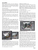
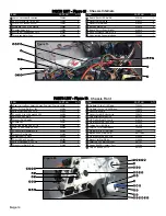
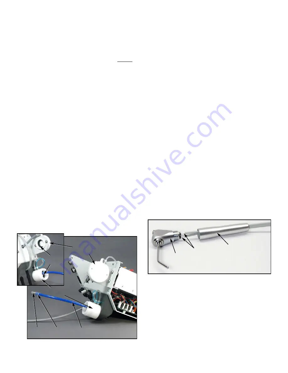
WATER RESERVOIR CAP - Fig. 6
Remove the pump cover as previously described under
“Power Supply” disassembly procedure. Disconnect the
pressure gauge tubing at the 4-way connector. Remove the
pressure gauge. Disconnect the two tubes in the rear of the
cap. Remove the two screws holding the cap with a 1/8-inch
Allen wrench. Remove the seal and fittings from the old cap
and install onto new cap.
Reassemble cap in the reverse order.
WATER PICK-UP TUBE - Fig. 6
Remove the water bottle. Gently pry and slide tube clamps
away from fittings at the filter and the cap. Remove tube.
Replace tube with existing filter and clamps installed.
WATER FILTER - Fig. 6
Remove the water bottle. Gently pry and slide tube clamps
away from the filter. Remove the filter and clean or replace
if clogged. Use existing fitting when installing new filter.
AIR & WATER SEALS - Fig.6
Remove the appropriate bottle. Lift out the seal from the
cap and replace with a new seal. Ensure that seal is properly
seated in the cap.
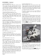
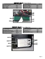
SYRINGE - Fig. 7
Unscrew the handle from the syringe head. Remove the
tubes from the syringe head. Remove the tube clamps from
the tube and remove the handle.
Reassemble syringe by placing the tube through the handle
and placing the tube clamps on the tube. Place the tube
with the line on the inner side of the tube to the water side.
Attach the handle to the syringe head and test for air, water
and spray.
OVERLAY
The chassis does not have to be removed to replace the
overlay. Peel a corner of the overlay away from the chassis
console with an exacto knife or sharp-edged tool and pull the
overlay off the console.
To replace the overlay, align the new overlay with the console
LEDs and press into position using hand pressure. NOTE: To
help realign the overlay into position, it is recommended that
a battery pack be connected to the console and all the LEDs
turned on.
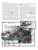
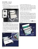
FAN & FAN GUARD - Fig. 16
Remove the pump cover as previously described under
“Power Supply” disassembly procedure. Using a #2 Phillips
head screwdriver and 1/4-inch wrench, remove the four
screws which hold the fan guard and fan to the chassis.
Reassemble fan and guard in the reverse order.
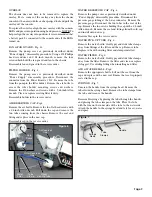
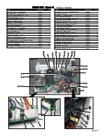
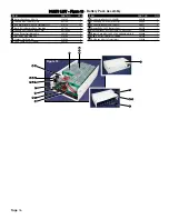
FILTER HOLDER - Fig. 4
Remove the pump cover as previously described under
“Power Supply” disassembly procedure. Disconnect the
connector from the Power Board at ‘J13’. Remove the tube
from the pump to the filter holder. Remove the air bottle to
access the filter holder mounting screws and washers.
Remove the #6 washers and screws with a 5/64-inch Allen
wrench. Clean or replace existing filter if dirty.
Reassemble holder in the reverse order.
AIR RESERVOIR CAP - Fig.6
Remove the air bottle. Remove the two flat head screws with
a 1/8-inch Allen wrench. Pull down the cap and remove the
two tubes coming from the chassis. Remove the seal and
fitting and replace in the new cap.
Reassemble cap in the reverse order.
Figure 6
Water Reservoir
Cap
Water
Filter
Air Reservoir
Cap
Water
Pick-Up Tube
Tube
Clamp
Cap
Seals
Figure 7
Tube
Clamps
Syringe
Head
Handle

