background image

13

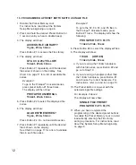
7. The display will show:

ACCESS FIlE lIBRARy?

1=yes, 2=no, 3=esc

Press Button #2.  Do not access

the file library.

8. The display will show:

SAvE CURRENT SETTINGS?

1=yes, 2=no, 3=esc

Press Button #1 to record settings on the

Preset Button.

9. The display will resemble the following:

(The handpiece ratio, speed and torque

values will vary according to your settings).

USER dEFINEd PRESET

1/8 AG     300     240

The Preset Button is now programmed with

the specified settings.

10. When you have completed the

programming of the desired preset buttons,

re-enable the Preset Memory Lock to avoid

inadvertently entering the File Library

during a procedure.  For instructions, read

about the System Setup Menu beginning

on page 6.

1. Disable the Preset Memory Lock and enable

or disable Auto Stop Reverse and torque

warning tone.

For instructions, read about the System

Setup Menu beginning on page 6.

2. Set the Handpiece Ratio to the correct

setting.

Press the Handpiece Ratio Selector up or

down arrows until the Handpiece Ratio

Indicator matches the ratio of the handpiece

to be used.

3. Set the speed to the desired setting.

Press the Speed Selector up/down arrows

until the desired speed is shown on the

display.

4. Set the torque level to the desired setting.

Press the Torque Selector up/down arrows

until the desired torque is shown on the

display.

To operate the motor at full torque, press the

"MAX" Torque Button.  The LED above the

"MAX" Torque Button will display a steady

red light, the Torque Indicator on the display

will read "MAX".  Operating at max. torque

will override the Auto Stop Reverse feature.

5. Set Handpiece Rotation to the desired

direction.

Press the Forward/Reverse Selector to

change the direction of handpiece rotation.

A red L.E.D. light above the

Forward/Reverse Selector indicates reverse

rotation.

6. Press and hold the desired Preset Button for

1 second (until you hear a double beep).

11. PROGRAMMING A PRESET BUTTON WITH A USER dEFINEd PRESET

Summary of Contents for AEU-25

Page 1: ...Endo DTC DIGITAL TORQUE CONTROL DUAL VOLTAGE TM OPERATION and MAINTENANCE INSTRUCTION MANUAL AEU 25 Electronic Endodontic System ...

Page 2: ...anty Back Cover Console Size 3 5 x 5 x 7 9 cm x 13 cm x 18 cm Console Weight 3 55 lbs 1 6 kg Power Source Dual Voltage 115V or 230V AC Power Consumption Maximum 100 W approx Sleep Mode 6 W SPECIFICATIONS To prevent injury to people and damage to property please heed relevant warnings and remarks They are marked as follows WARNING Serious injury or death may result if ignored CAUTION Damage to prop...

Page 3: ...or These features combine to make the perfect rotary file system for endodontic and other dental procedures Congratulations This system is engineered to provide many years of reliable service Please read the instructions provided in this manual to receive the best and longest service from your Aseptico equipment Separate manuals may be provided to cover the operation and maintenance of handpieces ...

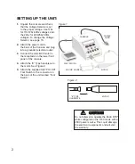
Page 4: ... 3 Connect the AE 4B 30 motor to the receptacle on the lower front panel of the console 4 Attach the E Type handpiece to the motor See Figure 2 5 Attach the supplied AE 7P On Off Foot Switch to the connector on the back of the unit marked Foot Switch 2 POWER CORD CONSOLE MOTOR FOOT SWITCH E TYPE HANDPIECE MOTOR MOTOR HOLDER Do not attempt to operate the Endo DTC while configured in the 115V mode w...

Page 5: ...le Front Figure 4 Console Back Handpiece Ratio Selector Speed Selector Calibration System Setup PRESET MEMORY LOCK RECALL FACTORY SETUP AUTO STOP REVERSE REVERSE BEEPER TORQUE WARNING TONE ACCESSORY WARNING TONE SLEEP MODE Preset Buttons Torque Selector Forward Reverse Maximum Torque Selector See page 6 for ADVANCED OPERATION AND FUNCTIONS ...

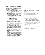
Page 6: ...ntic rotary file series you are using By default the Endo DTC preset buttons are set for the file series shown in Chart 1 Pressing the Preset Button repeatedly will cycle through the individual files listed below each series name 5 Press the foot pedal to activate motor and begin operation When using the optional AE 7D Dual Foot Control The black right side pedal controls the on off operation of t...

Page 7: ... 10 and 08 taper File 5 GT Blue 30 Series 06 and 04 taper File 6 GT Black 40 Series 10 and 08 taper File 7 GT Black 40 Series 06 and 04 taper Preset Button 4 Default File Series DENTSPLY Tulsa Dental Specialties ProTaper Universal Files File 1 ProTaper Universal S1 SX File 2 ProTaper Universal S2 F1 File 3 ProTaper Universal F2 F3 F4 F5 File 4 ProTaper Universal Retreatment D1 D2 File 5 ProTaper U...

Page 8: ...is greatly reduced Torque settings are held in memory even after unit is turned off For most endodontic root canal applications the included 1 8 reduction contra angle handpiece is normally used Proper contra angle maintenance including cleaning and lubrication are essential to minimize torque losses when using the torque reduction settings 4 FORWARd REvERSE SElECTOR FWd REv Determines the rotatio...

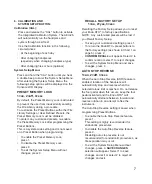
Page 9: ...t the System Setup Menu without changes press 3 SAvE CHANGES selection will appear Select 1 to save changes and exit or select 2 to reject all changes and exit 6 CAlIBRATION ANd SySTEM SETUP BUTTON Calibration CAl Press and release the CAL button to activate the Integrated Calibration System The AEU 25 will automatically run the handpiece and system through a self test Use the Calibration function...

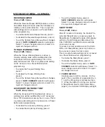
Page 10: ...audible when a GT Accessory file or ITR Emulation Accessory file is in use This is a system wide setting and is not saved on a Preset Button when programming To disable the Accessory Warning press 1 To enable the Accessory Warning press 2 To exit the System Setup press 3 SAvE CHANGES selection will appear Select 1 to save changes and exit or select 2 to reject all changes and exit SlEEP MOdE 1 on ...

Page 11: ...everse By default the Preset Buttons are programmed to recall the file series shown in Chart 1 on page 5 The Preset Buttons are also used to navigate the various menus in the System Setup and File Library The Preset Buttons can be customized to suit individual preferences There are three ways to program a preset button The Preset Buttons can be programmed with 1 An Entire File Series from the File...

Page 12: ...he System Setup Menu beginning on page 6 1 Disable the Preset Memory Lock For instructions read about the System Setup Menu beginning on page 6 2 Press and hold the desired Preset Button for 1 second until you hear a double beep 3 The display will show ACCESS FIlE lIBRARy 1 yes 2 no 3 esc Press Button 1 to access file library 4 The display will show GT ACC 20s yEllOW 1 next 2 ok 3 esc Press Button...

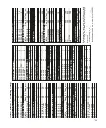
Page 13: ...6 35 Thru 06 50 500 368 VORTEX 06 25 06 30 500 290 VORTEX 06 15 06 20 500 195 GT Series 20 30 40 File Size Speed RPM Torque g cm GT ACC 90 70 50 35 12 500 700 GT YEL 20 10 20 08 300 312 GT YEL 20 06 20 04 300 174 GT BLU 30 10 30 08 300 347 GT BLU 30 06 30 04 300 208 GT BLK 40 10 40 08 300 405 GT BLK 40 06 40 04 300 230 PROFIlE S29 06 TAPER File Size Speed RPM Torque g cm PF S29 06 SIZE 7 6 300 368...

Page 14: ...dure For instructions read about the System Setup Menu beginning on page 6 1 Disable the Preset Memory Lock For instructions read about the System Setup Menu beginning on page 6 2 Press and hold the desired Preset Button for 1 second until you hear a double beep 3 The display will show ACCESS FIlE lIBRARy 1 yes 2 no 3 esc Press Button 1 to access the File Library 4 The display will show GT ACC 20s...

Page 15: ...age 6 2 Set the Handpiece Ratio to the correct setting Press the Handpiece Ratio Selector up or down arrows until the Handpiece Ratio Indicator matches the ratio of the handpiece to be used 3 Set the speed to the desired setting Press the Speed Selector up down arrows until the desired speed is shown on the display 4 Set the torque level to the desired setting Press the Torque Selector up down arr...

Page 16: ...ng the assembly remove any handpiece from motor and install autoclaving plugs into the end of the motor and motor cord connector as shown below The plugs are supplied with the motor and cord Loosely coil the motor cord when auto claving Avoid sharply bending the cord when autoclaving NOTE Call Aseptico Inc at 1 800 426 5913 for any questions or clarifications on this sterilization procedure Always...

Page 17: ...g voltage replace the fuses with fuses that are rated for the new voltage Turn the Fuseholder until the white lettering with the proper voltage is right side up 4 Replace the Fuseholder and close the Fuse Voltage Selector Panel 5 Select a power cord or grounded plug adapter specific to the country of use Turn the power off and unplug the unit before following the steps below WARNING 1 2 4 3b Do no...

Page 18: ...15 volts 0 5A 250V slo blo fuse for 230 volts Check motor plug connection Check foot switch connection Depress foot switch Check that a file is properly seated in the handpiece and the latch is closed Verify that ratio setting matches handpiece ratio Use Calibration function Turn power switch off wait 5 seconds then turn back on to reset Dirty under lubricated handpiece Handpiece lubricant is runn...

Page 19: ...levels of radio frequency RF emissions from electrical devices such as cellular phones may disrupt the performance of this device To mitigate disruptive electromagnetic interference position this device away from RF transmitters and other sources of electromagnetic energy SYMBOL DEFINITIONS Type B Equipment Dangerous Voltage Attention Consult Accompanying Documents The UL 2601 Standard Duty Cycle ...

Page 20: ...ch action In the event of alleged defect under warranty the purchaser is to notify Aseptico s Customer Service Department promptly Customer Service will provide instructions usually directing that the product be returned for service Shipment to Aseptico and the cost thereof is always the responsibility of the purchaser Accidental misuse inappropriate installation or failure to perform directed mai...

Reviews: