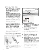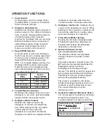
FIG. 4 - WASTE TANK CONNECTIONS
OUT (White)
IN (Gray)
Electrical Connector (Black)
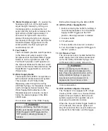
HANDPIECE
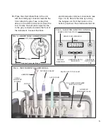
RATIO SELEC-
TOR
SPEED (RPM) SELECTORS
SPEED (RPM) INDICATOR
HANDPIECE RATIO
INDICATOR
FWD/REV
SELECTOR
FIG. 5 - ELECTRIC CONTROL CONSOLE
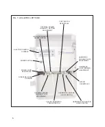
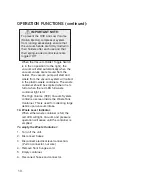
HANDPIECE
3-WAY
AIR/WATER
SYRINGE
HVE VACUUM
SALIVA EJECTOR VACUUM
AIR/WATER
PRESSURE GAUGE
FIG. 6 - INSTRUMENT HOLDER DETAIL
FULL WASTE CONTAINER
INDICATOR LIGHT
5.
10.
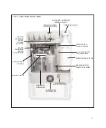
Place the small Waste Tank in the unit
with the small gray connector towards the
front. Attach the gray hose coming from
above to the white connector. Connect the
Low Volume Vacuum (saliva ejector) line
to the gray connector towards the front of
the instrument. Connect the black
MOTOR
OPTIONAL SCALER
electrical waste container connections (see
Figs. 4 & 8). Secure the tank by running
the bungee cord from the hooks on the
bottom panel over the small waste tank lid.


