background image

12

STERILIZATION & MAINTENANCE - 

Cont'd

:

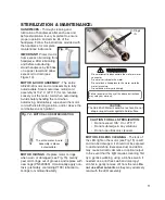
O-RING

INSTALLER

SLEEVE

FIG. 17 

INSTALLER

PIN

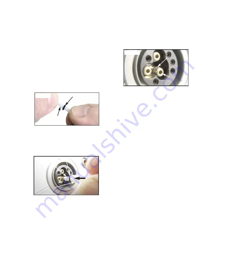
MOTOR/CORD RECEPTACLE O-RINGS

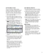
The O-rings for the three water/air ports in

the motor/cord receptacle should be replaced

if damaged or worn. Use the provided O-ring

installer pin and sleeve to replace the

O-rings:

1. Remove old O-ring from water or air port

fitting.

2. Slide new O-ring over pointed end of

installer pin, onto the pin’s shank (see

Figure 16).

3. Insert pointed end of installer pin into open

end of installer sleeve until O-ring stops

against end of tool. 

4. Position concave end of installer pin

against end of water/air port fitting (see

Figure 17).

O-RING

INSTALLER

PIN

FIG. 16 

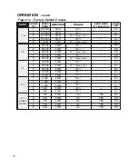
5. Push installer sleeve inward, until new O-ring

seats into groove on fitting (see Figure 18)

.

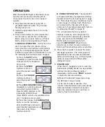
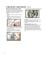
CONSOLE

- The exterior of the console may

be cleaned by wiping with a soft cloth

moistened with mild detergent or disinfecting

solution.

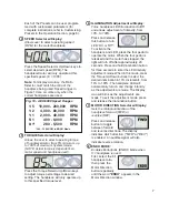
INTERNAL WATER LINE FLUSH

-

Thoroughly flush the water line inside the unit

with clean water for about 5 seconds after

every patient, and about 20 seconds at the

beginning of each day. After flushing the line,

use compressed air to purge any fluid in the

the line and leave the line dry until next clinical

use.

O-RING

FIG. 18 

WATER/AIR

FITTING

Summary of Contents for AEU-5000

Page 1: ...OPERATION AND MAINTENANCE INSTRUCTION MANUAL AEU 5000 Dental System AEU 5000 Dental System...

Page 2: ...t degree of protection against ingress of water Not suitable for use in the presence of a flammable anesthetic mixture with air or with oxygen or nitrous oxide INFORMATION CONCERNING THE ACCURACY AND...

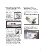
Page 3: ...t Separate manuals may be provided to cover the operation and maintenance of handpieces or other accessories for your unit PACKAGE CONTENTS AEU 5000 Control Console Autoclavable Micromotor P N AE 240...

Page 4: ...e guidelines when operating the unit Never touch drills burs or other handpiece tips when they are still rotating Handpieces should only be attached when the motor has stopped running WARNING Do not i...

Page 5: ...ing endodontic and other dental procedures WARNING Always use irrigating coolant when using high speed handpieces WARNING Do not use the AEU 5000 for implant surgery or where the cooling air can acces...

Page 6: ...LE NOTE A portion of the drive air input is used to cool the motor and handpiece This air vents around the LED and through the E coupling to the handpiece IMPORTANT Refer to the handpiece manual for r...

Page 7: ...7 Foot Control The existing foot control used to operate the office dental delivery system will now operate the AEU 5000 For variable pressure foot control note that the motor speed is proportional t...

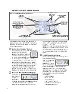
Page 8: ...ngs 2 Handpiece RATIO Selector w Display Allows user to select ratio of handpiece being used Press the Ratio Button repeatedly until the ratio of the handpiece being used is displayed When displayed t...

Page 9: ...justment w Display Turns handpiece LED illumination On Off and allows adjustment of intensity from 10 to 100 Press and release this button to turn LED On or Off To activate the handpiece and LED press...

Page 10: ...ndpiece LED On Off Press and hold to enter intensity adjustment mode then adjust using Torque Up Down buttons B PRESET OPERATION The AEU 5000 is shipped with five preprogrammed factory Presets for eac...

Page 11: ...he user attempts to disable the last operational ratio the system will emit a beep sound and ignore the user s command to disable this remaining option NOTE If the factory defaults are restored all cu...

Page 12: ...D 100 Off 2 60 000 FWD 100 Off 3 60 000 FWD 50 Torque Limit Off 4 40 000 FWD 100 Off 5 40 000 FWD 50 Torque Limit Off 5 1 1 2 000 FWD 100 On 2 1 500 FWD 100 On 3 1 200 FWD 100 On 4 800 FWD 100 On 5 40...

Page 13: ...Occasionally apply non toxic preferably containing PTFE lubricant to O rings to maintain flexibility MOTOR LED LENS CLEANING The lens of the LED light on the motor see Fig 15 is soft and can be damage...

Page 14: ...ing stops against end of tool 4 Position concave end of installer pin against end of water air port fitting see Figure 17 O RING INSTALLER PIN FIG 16 5 Push installer sleeve inward until new O ring se...

Page 15: ...reattach connector If above procedure doesn t correct the problem then return unit to the factory for repair Check motor plug connection Depress foot switch Increase Speed Increase Torque setting Che...

Page 16: ...ompanying documents Type BF Equipment Do Not Throw In Trash Class II Equipment Manufacturer Authorized European Representative Protective Earth Ground Motor Direction Light Controls Temperature Limita...

Page 17: ...nlet is the mains disconnect means Qualified Power Supplies TrumPower TRM60 S48 4G 510 TRM60 S48 4G 5095RG Astec DPS58 M DPS58 M 760K Advanced Power Solutions MPU50A 8 1013 3 hPa 697 hPa 10 90 10 C 50...

Page 18: ...or whole Aseptico shall be the sole arbiter of such action In the event of alleged defect under warranty the purchaser is to notify Aseptico s Customer Service Department promptly Customer Service wil...

Page 19: ...17 NOTES...

Page 20: ...P N 420819 Rev E ECO 14684 03 2019 PRINTED IN THE USA P O Box 1548 Woodinville WA 98072 8333 216th Street S E Woodinville WA 98072 425 487 3157 800 426 5913 www aseptico com info aseptico com...

Reviews: