4
1.
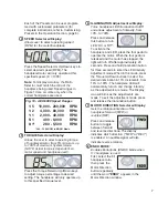
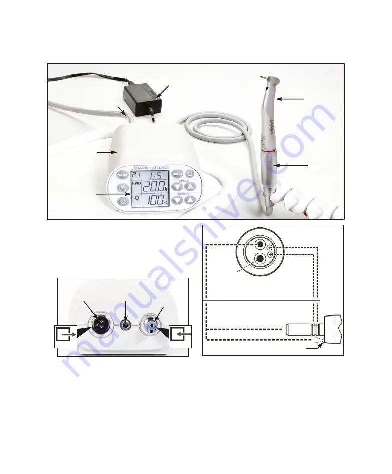
Unpack the Console and accessories (see
Figure 1).
2.
Attach the 4-hole handpiece tubing connector
from the office dental system to the
receptacle on the back of the AEU-5000
console (refer to
INPUT
symbol in Figure 2).
3.
Note the alignment of the four air/water ports
on the AEU-5000 receptacle with the four
holes on the handpiece tubing connector.
IMPORTANT:
Ensure that all tubing
supplying the unit is properly connected and
that the air and water are delivered to the
console as shown in Figure 3
Fig. 2 - Console Back
MOTOR/CORD
RECEPTACLE
48VDC
POWER INLET
4-HOLE
HANDPIECE
TUBING
RECEPTACLE
NOTE:
A portion of the drive air input is used to cool
the motor and handpiece. This air vents around the
LED and through the E-coupling to the handpiece.
IMPORTANT:
Refer to the handpiece manual for
recommended pressure for chip irrigation air and water,
typically in the range of 10-30 PSI (0.68-2.06 bar). It is
recommended to turn off chip air and water when using
handpieces that do not support irrigation.
SETTING UP THE UNIT:
Fig. 1 - System Components
CONTROL
CONSOLE
LCD
DISPLAY
4-HOLE HANDPIECE
TUBING FROM OFFICE
DENTAL SYSTEM
MOTOR
w/CORD
48 VDC EXTERNAL POWER SUPPLY
(100-240 VAC, 50-60HZ, POWER SOURCE )
HANDPIECE
(Sold Separately)
Fig. 3
CONSOLE AIR/WATER INPUT
MOTOR AIR/WATER OUTPUT
(EXHAUST)
DRIVE AIR
CHIP AIR
CHIP WATER
(LED)
MOTOR
HANDPIECE COOLING AIR
HANDP'C COOLING AIR VENT
INPUT
OUTPUT

