5
4.
Attach the AE-240 motor cord to the motor
receptacle on the back of the console (refer
to
OUTPUT
symbol in Figure 2):
a)
Align the circular dimple on the motor
cord connector with the mark on the top
center of the motor receptacle (Figure 4).
b)
Push the cord
connector body
straight into the
receptacle to lock it
into place. To
disconnect connector,
pull it straight out.
5.
Attach the appropriate Aseptico "E-Type"
handpiece to the motor as shown in Figure 5.
6.
Attach the external power
supply connector to the
back of the console,
tightening the locking nut
(see Figure 6). Plug power
supply into a hospital
grade grounded electrical
receptacle. Confirm that the type of cord
plug is correct for the country of usage and
carries the proper certification markings.
7. Foot Control:
The existing foot control
used to operate the office dental delivery
system will now operate the AEU-5000. For
variable-pressure foot control, note that the
motor speed is proportional to the air
pressure delivered within a 20 PSI (1.36
bar) range, e.g., 5 PSI (0.34 bar) provides
minimum speed and 25 PSI (1.70 bar)
provides displayed speed.
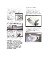
8. Under-Counter Installation:
An optional bracket is available for
mounting the AEU-5000 console under a
counter or onto a mobile delivery system
(see Figures 7 & 8). The adjustable
bracket allows chair-side viewing of the
LCD and convenient access to the control
panel.
The bracket comes equipped with all the
mounting hardware required for quick and
easy installation in a dental office or
operatory. Contact Aseptico for ordering
information.
Fig. 6
LOCKING NUT
Fig. 4
ALIGNMENT MARKS
Fig. 5 - Handpiece/Motor Connection
ALIGNMENT
PIN
HANDPIECE
MOTOR
Fig. 7 - Optional Mounting Bracket
Fig. 8 - Under Counter Installation

