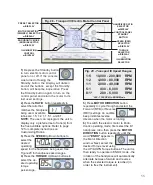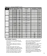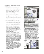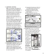
10.
be 'On' and the instrument removed from its
holder before operation can begin.
NOTE:
The HVE and saliva ejector are not
controlled by the Foot Control - they will
automatically start when removed from their
holders and their toggle switches are On.
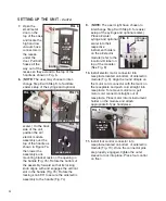
4. INSTRUMENT CONTROLS
(Figs 26 & 27)
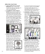
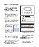
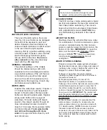
The Transport III includes controls for the
motor, vacuum valve holders, and optional
scaler. These holders include an On/Off
toggle switch
(Fig. 26)
which when
turned 'Off'
(toggle to the
left), keeps
the instrument
off, even when
removed from
its holder. When the toggle switch is
turned 'On' (toggle toward the red dot), the
instrument will automatically activate when
removed from its holder.
5. ELECTRIC MOTOR AND CONTROL
PANEL
(Fig. 28) - There are two different
control modes that can be used to operate
the Transport III electric motor: Manual
Mode using the console buttons, or Preset
Mode using the preprogrammed Presets:
A. MANUAL OPERATION
- When the
electric motor is not running, the user can
adjust its ratio, speed, torque, motor
direction, and motor LED settings using the
control panel keypad (The Preset indicator
in upper left of LCD display will blink on and
off, indicating the change):
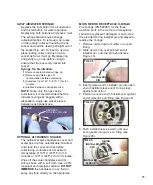
1. ON/OFF POWER SWITCH & CIRCUIT
BREAKER
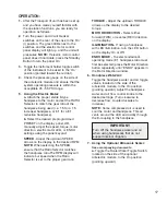
(Fig. 24) - Controls power
On/Off to the Transport III. When the unit is
turned On, the green LED next to the
power switch will illuminate.
2. COMPRESSOR CIRCUIT BREAKER
SWITCH
(Fig. 24) When the switch is On
(circuit closed/continuity complete), the
compressor will start and the green LED
next to the switch will illuminate. When the
switch trips open (continuity interrupted)
due to a compressor overload, the switch
and LED turn Off. Simply turn the switch
back On to reset breaker.
NOTE:
If switch
is found in a neutral position (midway
between On and Off), find and correct the
fault then turn the switch to the On
position.
IMPORTANT:
The switch should
be left in the On position when not in use.
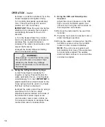
3. ON/OFF FOOT CONTROL
(Fig. 25) – The
Foot Control provides On/Off operation to
the motor, water, and air coolant to the
handpiece, and the handpiece light, when
the electric motor is removed from its
holder and its water & air toggle switches
are toggled ‘ON’. The Foot Control also
provides On/Off opera-
tion to the optional
ultrasonic scaler and
water coolant to the
scaler when the scaler
is removed from its
holder and the water
toggle switch is toggled
‘ON’. For instrument
operation, apply foot pressure to any part of
the disk. The instrument holder toggle must
OPERATION FUNCTIONS:
APPLY PRESSURE
TO ACTIVATE
INSTRUMENT
FIG. 25
FIG. 27
HVE
ELECTRIC
HANDPIECE
SALIVA
EJECTOR
FIG. 26
ON
OFF
SYRINGE
PWR
ON/OFF
FIG. 24
COMPRESSOR
CIRCUIT
BREAKER
OPTIONAL
SCALER

