background image

4.

7.

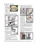
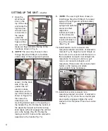
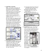
Open the

small metal

door on the

top of the case

and locate the

high and low

vacuum hose

connectors in

the recess

under the

door. Pull both

hoses all the

way out of the

recess so they extend to the top of the

handle as shown in Fig. 6.

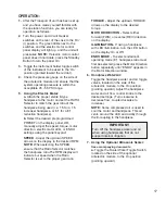
8.

(

NOTE:

The user may choose to inter-

change Step 8 with Step 9, to facilitate

easier setup of the syringe and optional

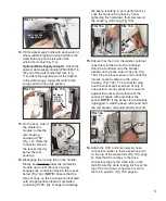
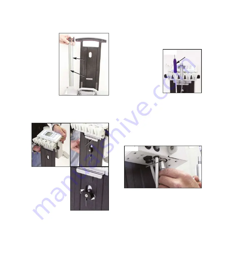
scaler.) On the back

side of the unit,

position the air/

electric module

assembly over the

top of the handle as

shown in Figure 7a,

then lower the

assembly so its

mounting bracket rests on the opening in

the handle (Fig. 7b). Rotate the bottom of

the assembly forward so that its locking

knob aligns with and engages the vertical

slot in the handle (Fig. 7b). Rotate the

locking knob 90° to secure the air/electric

assembly to the handle (Fig. 7c).

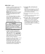
9.

(

NOTE:

The user might have chosen to

interchange Step 9 with Step 8, for easier

setup of the syringe and optional scaler.)

Place air/water

syringe and optional

scaler into their

respective

instrument holders

on the air/electric

module (refer to the

location-ID label on

top of the module).

(See Fig. 8)

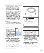
10.

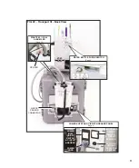
Install electric motor connector into

receptacle located on bottom of air/electric

module (Fig. 9). Align the round dimple on

the motor cord connector with the mark on

the receptacle and push cord straight into

receptacle. To remove motor/cord, pull

motor cord connector straight out of

receptacle. Place motor into its instrument

holder on the module and attach

appropriate E-Type handpiece.

11.

Install foot control connector into

receptacle located on bottom of air/electric

module (Fig. 10). Once the connector pins

are properly engaged, tighten the outer

sleeve to lock into place. Place foot control

on floor.

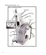
SETTING UP THE UNIT - 

Cont’d

FIG. 7b

FIG. 7c

FIG. 7a

LOCKING KNOB

LOCKING KNOB

FIG. 9

MOTOR

CONNECTOR

ALIGNMENT

DIMPLE

MOUNTING

BRACKET

FIG. 8

OPTIONAL

SCALER

FIG. 6

HIGH

VACUUM

HOSE

LOW 

VACUUM

HOSE

(DOOR)

Summary of Contents for AEU-525 Transport III

Page 1: ...OPERATION MAINTENANCE MANUAL AEU 525 AEU 525S Portable Dental System Transport III...

Page 2: ...R USE The AEU 525 IFU TRANSPORT III PORTABLE DUAL VOLT UNIT 110 220V AEU 525S TRANSPORT III W SCALER DUAL VOLT UNIT 110 220V is a portable self contained dental system that is used for endodontic and...

Page 3: ...rate manuals may be provided to cover the operation and maintenance of other accessories for your unit PACKAGE CONTENTS Portable Case with Electronic Control Compressor and Vacuum Pump AE 230M 40 Moto...

Page 4: ...event the proper function of cardiac pacemakers Therefore Aseptico recommends that patients with a cardiac pacemaker should not be treated with the Ultrasonic Scaler component of the AEU 525S System W...

Page 5: ...the outside of the rear metal door Fig 4b Turn fastener counter clockwise 1 4 turn to loosen Stand unit upright Use the fastener tool to loosen the two fasteners on the small metal door located on th...

Page 6: ...9 with Step 8 for easier setup of the syringe and optional scaler Place air water syringe and optional scaler into their respective instrument holders on the air electric module refer to the location...

Page 7: ...to place by hand tightening the hold down thumb screw on the housing until snug Fig 13b 15 Ensure that the lid on the waste container is securely latched onto the container Hang the container onto the...

Page 8: ...s as a circuit breaker for the whole unit The right hand switch acts as a circuit breaker for the compressor Electrical overloads will trip the two switches If either switch is found in a neutral posi...

Page 9: ...CONTROL WASTE CONTAINER LCD DISPLAY SALIVA EJECTOR SYRINGE SCALER ELECTRIC MOTOR ELECTRIC MOTOR CONTROL PANEL Pages 10 13 MANIFOLD PANEL Pages 14 15 SCALER CONTROLS HANDPIECE WATER CONTROLS PRESSURE...

Page 10: ...OTTLE HVE HOSE SETTING UP THE UNIT Cont d AIR ELECTRIC MODULE ASSEMBLY FOOT CONTROL HIGH VACUUM HOSE WATER BOTTLE PURGE SWITCH SALIVA EJECTOR HOSE LOW VACUUM HOSE INSTRUMENT HOLDERS Page 10 ON OFF LEV...

Page 11: ...ULL ALARM LED Page 16 WATER BOTTLE PURGE SWITCH Page 6 COMPRESSOR ON OFF SWITCH CIRCUIT BREAKER POWER ENTRY AND CIRCUIT BREAKER PANEL Page 6 115V 230V VOLTAGE SELECTOR SWITCH POWER INLET ON OFF SWITCH...

Page 12: ...ower On Off to the Transport III When the unit is turned On the green LED next to the power switch will illuminate 2 COMPRESSOR CIRCUIT BREAKER SWITCH Fig 24 When the switch is On circuit closed conti...

Page 13: ...to turn on the control panel and return the motor to its last used settings 2 Press the RATIO button repeatedly to select the ratio that matches the handpiece being used Available ratios are 1 5 1 2 1...

Page 14: ...ILLUMINATION button to turn the hand piece LED On Off To activate the handpiece and LED remove the handpiece from its holder turn the Illumination button On and press the foot pedal to operate the mo...

Page 15: ...FWD 100 Off 2 60 000 FWD 100 Off 3 60 000 FWD 50 Torque Limit Off 4 40 000 FWD 100 Off 5 40 000 FWD 50 Torque Limit Off 5 1 1 2 000 FWD 100 On 2 1 500 FWD 100 On 3 1 200 FWD 100 On 4 800 FWD 100 On 5...

Page 16: ...bgingival scaling furcations supragingival fine scaling and spot removal The 38 tip is used for lingual and buccal subgingival scaling and furcations The 39 tip is used for universal lingual and bucca...

Page 17: ...rd position to turn handpiece water On or downward to turn it Off A water control valve is also provided to adjust the volume of water flow to the handpiece This valve is located next to the toggle va...

Page 18: ...Low Volume Saliva Ejector compressor system from running excessively ensure that the vacuum heads are firmly cradled in their holders after each use and that their control levers are toggled Off beep...

Page 19: ...er the Transport III unit has been set up and you have made yourself familiar with the operation functions you are ready for operation as follows 2 Turn the power and circuit breaker switches on the r...

Page 20: ...b Adjust the water and air flow by using a screwdriver to turn the two small adjustment screws located on the side of the air electric module Upper screw controls water lower screw controls air Turn...

Page 21: ...assembly at 132 C 270 F for ten minutes Loosely coil the motor cord when autoclaving Avoid sharply bending the cord when autoclaving Alternatively wipe down the motor cord with disinfecting solution...

Page 22: ...aming cleansers in the vaccum lines AIR BOTTLE FILTER Routinely check the air bottle filter once a day for condensation To drain condensation place a towel or container below the filter and use pliers...

Page 23: ...ips are fully autoclavable Disinfect and clean the cover and tips before autoclaving Autoclave at a maximum temperature of 135 C 275 F for 10 minutes or 120 C 248 F for 20 minutes Wipe off the scaler...

Page 24: ...wn in Fig 46 10 Coil the two power cords and position on top of the waste tank and air bottle as shown in Fig 46 11 Carefully close case lid taking care not to pinch any internal components 12 Locate...

Page 25: ...r flow control valve to the handpiece is open counterclockwise Check that handpiece air toggle on side of air electric module is On Check that the air flow control valve to the handpiece is open count...

Page 26: ...100 MICRON WATER BOTTLE 730326 1 BOTTLE 1 LITER 32 OZ BLOW MOLDED HDPE WATER 730471 1 GASKET FOR AIR WATER BOTTLE LID 730473 3 FILTER AIR 1 4 NPT X 1 19 GAST INLET FILTER 730494 1 BOTTLE 750 ML 25 OZ...

Page 27: ...tion Atmospheric Pressure Limitation Type BF Equipment Motor Direction Light Controls Consult Instructions For Use Do Not Lift by Top Lid Or Latches Counterclockwise to Increase Open Clockwise to Decr...

Page 28: ...33 9 fl oz 1 0 liters Air Storage Capacity 25 4 fl oz 750 ml nominal Water Flow 5 07 fl oz min 0 15 liter min Waste Container Capacity 0 48 gallon total 0 24 gal per side 1 8 liters total 0 90 L per...

Page 29: ...ter of such action In the event of alleged defect under warranty the purchaser is to notify Aseptico s Customer Service Department promptly Customer Service will provide instructions usually directing...

Page 30: ...28 NOTES...

Page 31: ...29 NOTES...

Page 32: ...P N 420996 Rev K ECO 15011 06 2020 PRINTED IN THE U S A P O Box 1548 Woodinville WA 98072 8333 216th Street SE Woodinville WA 98072 425 487 3157 800 426 5913 www aseptico com info aseptico com...

Reviews: