6.
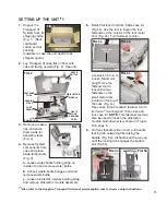
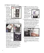
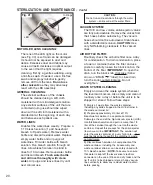
Place the HVE and saliva ejector valves
into their respective instrument holders on
the air/electric module (refer to the
location-ID label on top of the module).
Attach the desired evacuator/saliva ejector
tips into the valves.
17.
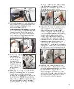
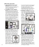
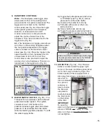
Attach the HVE and saliva ejector hose
connectors (black)
from Step # 6, page
3, to their
respective ports on
the top of the waste
tank (Fig. 16).
Rotate the black
locking latch
overtop the two
hose connectors to
secure them in place.
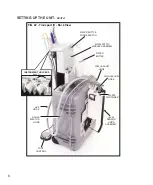
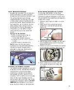
18.
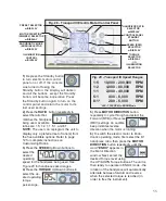
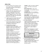
Toggle the water-bottle purge switch
located on the
back side of
the air/
electric
module to the
“PRESSURE”
position (Fig.
17).
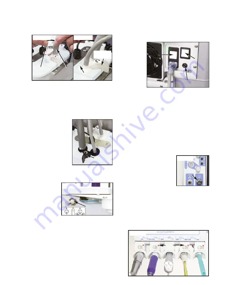
19.
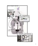
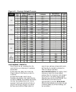
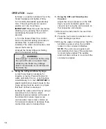
Verify that the voltage-selector switch
located on the motor housing is set to the
proper 115V or 230V power source (Fig.
18). Attach the power cord to the power
inlet receptacle and plug into a grounded
electrical outlet.
NOTE:
Ensure that the
power cord is correct for the voltage
source in the country of use.
Turn both rocker switches on the motor
housing to the ‘ON’ (I) position. The left-
hand
switch
turns
the unit
power
On/Off
and
also
acts as
a circuit
breaker for the whole unit. The right-hand
switch acts as a circuit breaker for the
compressor. Electrical overloads will trip
the two switches. If either switch is found
in a neutral position (midway between ‘ON’
and ‘OFF’), check for overload causes and
correct the problem. Then, place the switch
in the ‘ON’ position. Green LED’s adjacent
to each switch illuminate when the
switches are On.
NOTE:
When the unit is
in use, it’s compressor motor will
occasionally turn On and Off, to maintain
proper pressure.
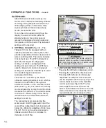
20.
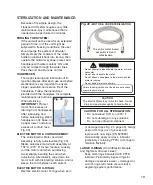
Ensure that the system
operating pressure is
maintained at 45-55 PSI
(3.10-3.79 bar). The
pressure gauge is
located on the side of
the air/electric module (Fig. 19).
21.
Turn all instrument holder and manifold
control panel toggle switches to the ‘ON’
position: toggle the instrument holders toward
the red dot (see Fig. 20); toggle the manifold
panel switches to the UP position (see Fig.
19).
NOTE
: If the vacuum comes on, reseat
the vacuum handpieces in their holders.
SETTING UP THE UNIT -
Cont’d
FIG. 16
ROTATING
LATCH
FIG. 17
WATER BOTTLE
PURGE SWITCH
FIG. 18
VOLTAGE SELECTOR
SWITCH
POWER
ON/OFF
COMPRESSOR
ON/OFF
FIG. 19
PRESSURE
GAUGE
FIG. 20
RED
DOTS
FIG. 15a
FIG. 15b
ALIGNMENT
TAB
HVE
HOSE
SALIVA
EJECTOR
HOSE
ROTATING
LATCH

