Page 8
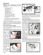
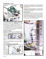
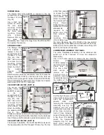
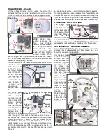
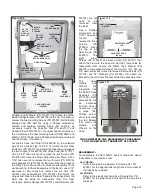
Note the orientation of the connectors' wiring with the
Board's connectors. Remove Power Board from Module and
set aside for reassembly later.
IMPORTANT:
The Power
Board Assembly is not a customer-serviceable item. Return
the Board Assembly to Aseptico if repairs are necessary.
Pull the inboard Insulator (PN 462113) off the four nylon
mounting Standoffs (PN 462112) (Fig. 28) and place aside
for reassembly later. Unscrew, by hand, the nylon Standoffs
from the threaded studs on the Module's Front Wall and set
Standoffs aside for re-assembly later.
MANIFOLD ASSEMBLY
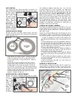
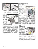
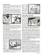
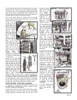
Locate the five mounting screws (PN 510037) for the
Manifold Assembly (PN 330591) and Manifold Wall (PN
462029) (Fig. 30), two on the top and two on the bottom of
the Module and
one on the face
of the Manifold
Control Panel.
Use a 5/64"
Allen wrench to
remove all four
screws.
Carefully pull the Manifold Assembly away from the Module
until the plumbing connections on the inboard side are
readily accessible.
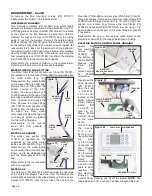
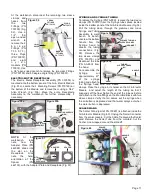
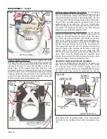
SCALER-ADJUSTMENT POTENTIOMETER
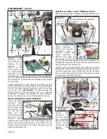
The
scaler
potentiometer
(part of PN
730691)
is
located on the
M a n i f o l d
Assembly (Fig.
31). Loosen the
small setscrew
on the side of
the potentio-
meter knob with
a 1/32" Allen wrench and remove knob. Remove the
mounting nut on the outboard side of the Manifold Wall with
a ½" socket or open-ended wrench. From the inboard side of
the Manifold, remove potentiometer through the hole in the
Wall (see Fig. 33).
Reassemble the scaler potentiometer in the reverse order
with the lock washer positioned against the inboard side of
the Maniflold wall and the alignment pin on the potentiometer
keyed into the hole in the Wall.
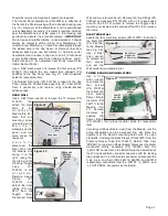
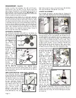
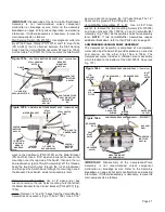
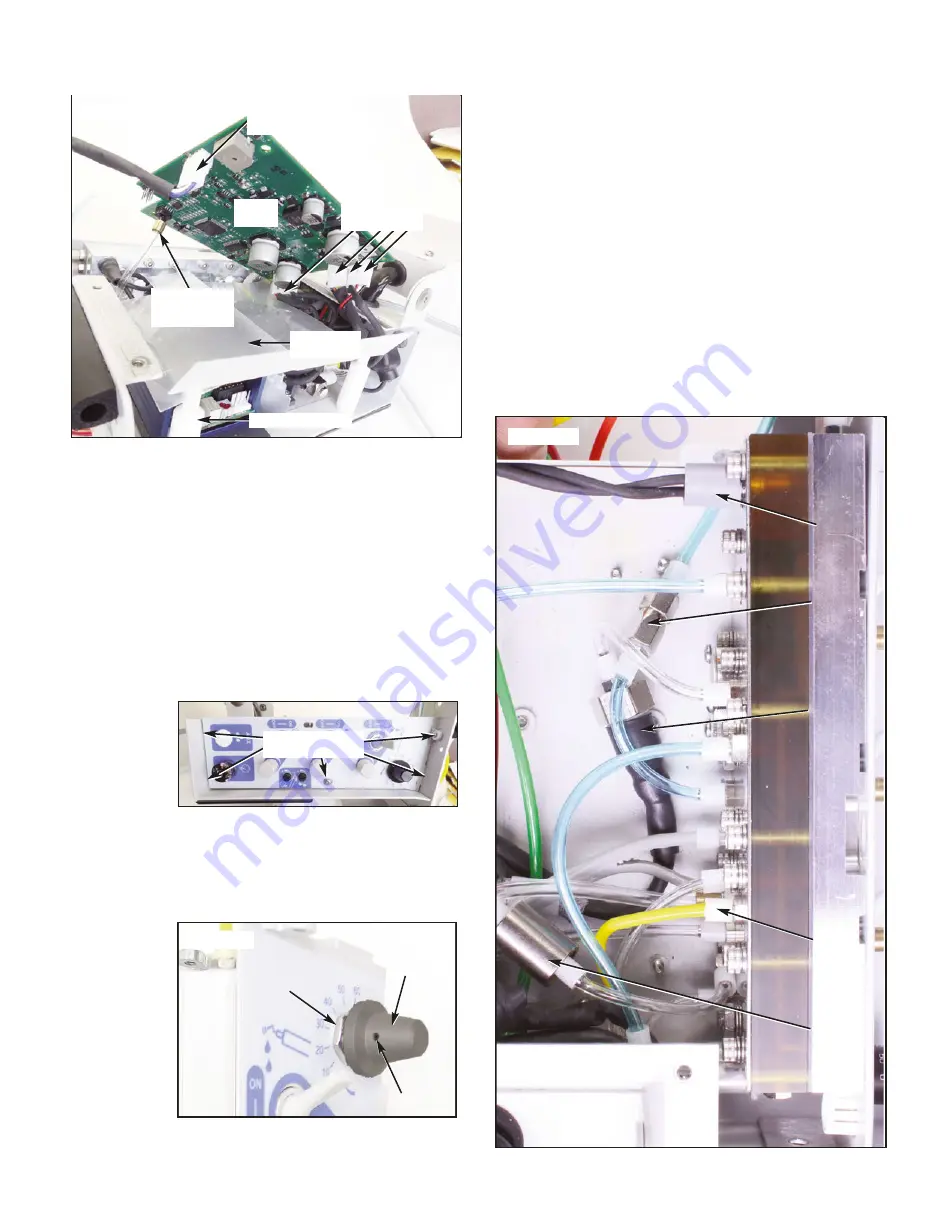
MANIFOLD BLOCK
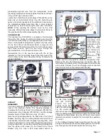
The On/Off and Air & Water Control Valves for the Scaler,
Motor/Handpiece, and Syringe are located on the Manifold
Block Assembly (Fig. 32). Cut the two wires to the Scaler
Disable Switch, PN 830144, located at the right top corner of
the back side of the Manifold (Fig. 32) and then unscrew
Switch by hand. When reassembling, note the lockwasher
(part of Switch) is positioned against the Block.
DISASSEMBLY - Cont'd
Figure 28
POWER
BOARD
INBOARD
INSULATOR
STANDOFFS (X4)
PRESSURE
SENSOR TUBE
AND CLAMP
DISPLAY BOARD
WIRE HARNESS
CABLE
CONNECTORS
Figure 30
MOUNTING
SCREWS (X5)
Figure 31
SETSCREW
SCALER
ADJUSTMENT
KNOB
MOUNTING
NUT
Figure 32
SCALER
ACTIVATION
SWITCH
SCALER
DISABLE
SWITCH
WATER
CHECK
VALVE
1/8" TUBE
SLEEVE
CLAMP
(TYP.)
35 PSI
REGULATOR


