Page 9
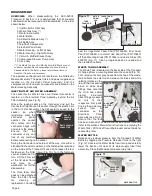
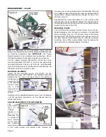
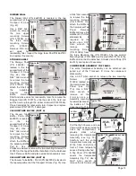
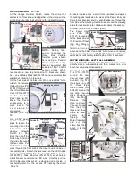
Use diagonal cutters or needle-nose pliers to pry off all
sleeve clamps from the tubing and hoses that connect to the
Manifold Block (Fig. 32). The 1/16" tubing is attached with
Sleeve Clamps PN 730152; the 1/8" tubing is clamped with
PN 730015 Clamps or PN 730096 Uni-Clamps; and, the
1/4" tubing is attached with either large white nylon Clamps
PN 730095; large brass Clamps PN 461607, or the large
aluminum Clamps PN 462230.
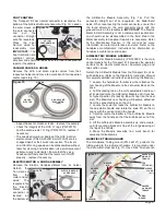
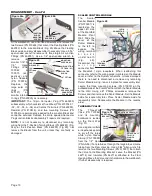
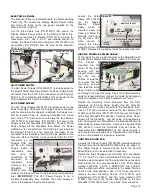
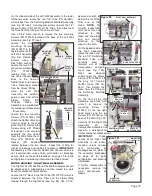
Detach the connecting tubes and hoses from Manifold
Block.
NOTE:
To simplify disassembly, at this time, only
detach the tubes and hoses that are still interconnected to
the Module Assembly -- leave the other tubes and hoses
with loose ends attached to the Block (Fig. 33). Take note
how all tubes and hoses connect to the Block. Inspect the
ends of all tubes and hoses for fraying or cracks and trim off
damaged ends before re-attaching to Block. Refer to
Plumbing Schematic Drawings for proper reassembly of
tubes and hoses.
Move Block to work bench for further disassembly. Detach
remaining sleeve clamps and tubes as necessary.
IMPORTANT:
The Manifold Block (Fig. 33) is not a customer-
serviceable item. Return the Block to Aseptico if repairs are
required.
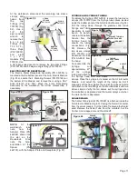
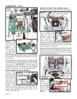
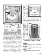
JUNCTION BLOCK
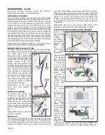
The Junction Block provides an interconnecting air, water,
and electrical terminal between the 525CF Control Module
and the Compressor Module. The Block is located in the
pivotal housing attached to the back side of the Air & Water
Figure 33
Manifold Module (Fig. 34a).
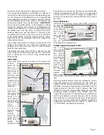
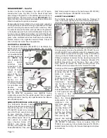
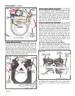
Use a 5/64" Allen wrench to remove the four mounting
Screws (PN 510037) that attach
the Front Housing (PN 462042)
to the Rear Housing (PN 462043)
(Fig. 34b).
Use diagonal cutters or needle-
nose pliers to pry off the sleeve
clamps from the two tubes and
hose that connect to the Junction
Block (Fig. 34a). The 1/8" tubing
is clamped with Clamps PN
730015 and the 1/4" hose is
attached with a large white nylon
Clamp (PN 730095).
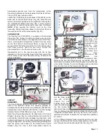
Use a small flat-head screwdriver to disconnect just the
Junction Block wiring from the 7-position Terminal Block (PN
860283) located inside the Rear Housing (Fig. 34a). Take
note of the color wiring-to-terminal connections, for
reassembly later. Note the wiring configuration of the
Resistor (PN 810438). Refer to the electrical schematic for
proper installation.
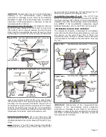
Locate the Locking Thumbscrew and Bracket (PN 462052)
on the side of the Rear Housing (Fig. 44a). Depress and
hold the Thumbscrew against the bracket while using a #2
Phillips screwdriver to remove the Junction Block mounting
screw (PN 510790). Remove the other mounting screws
(PN 510790) located on the opposite side of the Rear
Housing (Fig. 44b) and on the back side of the Housing.
Remove the Junction Block to the workbench for further
disassembly.
MOUNTING SCREWS
FRONT
HOUSING
JUNCTION BLOCK
Figure 34a
REAR
HOUSING
1/8" TUBE
SLEEVE
CLAMP (X2)
1/4" HOSE
SLEEVE
CLAMP
FUSE
HOLDER
7-POSITION
TERMINAL
BLOCK
CAPACITORS
(X2)
RESISTOR
(PN 810438)
Figure 34b

