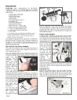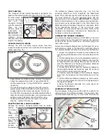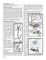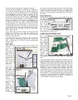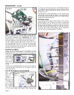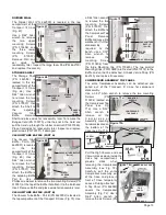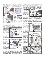
SCALER CONTROL MODULE
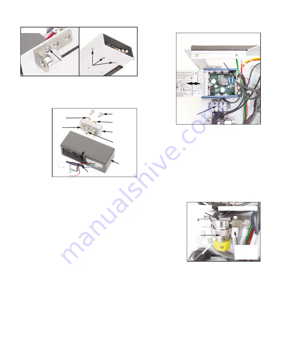
The
Scaler
Control Module
(PN 730691) is
located on the
upper left side
of the Manifold
Module Front
Wall. Slide the
cover of the
Scaler Module
to the left, to
expose
the
wiring terminal
b l o c k s
u n d e r n e a t h
(Fig.
49).
Disconnect the
w i r i n g
connector from
the Module's 12-pin receptacle. When reattaching this
connector, refer to the wiring guide imprinted on the Module
cover, or refer to the System schematic. Unless damaged,
there is no need to disconnect or remove any remaining
Scaler Module wiring - leave it in place for reassembly later.
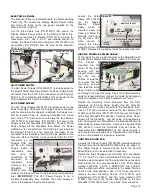
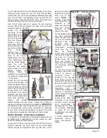
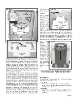
Locate the three mounting screws (PN 510530) on the
outboard side of the Front Wall that attach the Scaler Module
to the Wall. Using a #1 Phillips screwdriver, remove the
Screws and then remove the Scaler Module. Set the Module
aside for reassembly later. Place Scaler Module aside for
reassembly later. Reassemble the Module in the reverse
order.
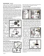
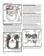
THREE-WAY VALVE
The
Three-Way
Valve (PN 730748)
and its mounting
hardware is located
on the Front Wall
(Fig. 51).
Use diagonal cutters
or needle-nose pliers
to pry off the large
white nylon Sleeve
Clamp (PN 730095)
from the 1/4" Hose
(PN AA-96) that protrudes through the large black silicone
tubing from the Rear Housing. Use a 5/64" Allen wrench to
remove the two Mounting Screws (PN 510037) that attach
the Valve to the Mounting Bracket. Leave the Bracket (PN
462114) and Insulator (PN 462116) attached to the Front
Housing. Move the Valve and its hardware to the workbench
if further disassembly is required.
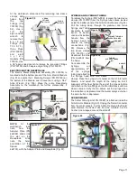
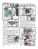
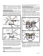
At the workbench, use a flat-head screwdriver to remove the
two Screws (PN 510688) that mount the Floating Block (PN
462052) to the Junction Block (Fig. 45). Move the Floating
Block aside and only disassemble if necessary: Use a 5/16"
open-ended wrench to remove its three large Air Junction
Fittings (PN 462051). Use a 1/4" open-ended wrench to
remove
its
smaller 1/16" &
1/8"
Hose
Fittings (PNs
730062
&
730073 res-
pectively) and
nylon Gaskets
(PN 730074).
Replace the
large outer O-
rings
(PN
520121),
or
smaller internal
O-rings (PN 520025) as necessary.
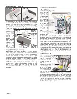
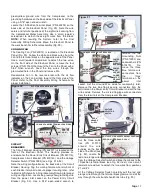
IMPORTANT:
The 12-pin Connector Plug (PN 860285)
subassembly, which consists of five Wires (PN's 870304-01,
-02, -03, -04, & -06) and Contact Terminals (PN 860290),
Resistor (PN 810438), and two mounting Screws (PN
510766) are permanently epoxied to the Junction Block and
cannot be serviced. Replace the entire epoxied Connector
Plug/Junction Block subassembly if repairs are required.
NOTE:
It is not necessary to disconnect any remaining
wiring from the 7-Position Terminal Block (PN 860283) (Fig.
34a) or the 4-Positon Block (PN 860250) (Fig 49), nor
remove the Blocks from the unit, unless they are faulty or
damaged.
Page 10
DISASSEMBLY - Cont'd
Figure 44a
JUNCTION
BLOCK
MOUNTING
SCREW
Figure 44b
MOUNTING
SCREWS (X3)
NON-
SERVICEABLE
CONNECTOR
PLUG ASSY
Figure 45
MOUNTING
SCREWS (X2)
AIR JUNCTION
FITTINGS (X3)
1/8" FITTING
1/16"
FITTINGS
(X2)
LARGE
O-RINGS (X3)
FLOATING
BLOCK
RESISTOR
Figure 49
12-PIN
CONNECTOR
BLOCK
4-PIN
TERMINAL
BLOCK
Figure 51
DETACH ONLY
THIS 1/4"
CLAMP &
HOSE
3-WAY
VALVE
MOUNTING
BRACKET
MOUNTING SCREWS (X2)

