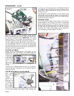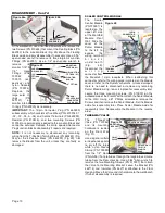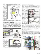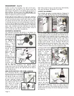
SYRINGE AND SYRINGE TUBING
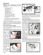
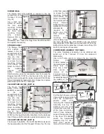
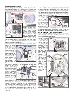
To replace the Syringe (PN TA-90D), remove the two sleeve
clamps (PN 730015) from the Syringe tube splices located
inside the bottom panel of the Air & Electric Module (Fig. 58).
Pull the tubing down through the grommet and move
Syringe and Tubing
Assembly to work
bench. At bench,
unscrew the bottom
handle from the
Syringe head to
access the tubing
connections (Fig.
59). Remove the
two sleeve clamps
(PN 730015) and
disconnect the tube
(PN AA-85G) from
the head.
To reassemble the
Syringe,
cut
approximately 67"
of the syringe
tubing and attach to
the Syringe head with two sleeve
clamps. Place the syringe in its holder on the Air & Electric
Module and adjust the length of the tubing so that it
suspends off the floor. Splice the end of the tube as before
and attach to the two fittings on the Manifold Block with two
sleeve clamps. Verify that air comes out the syringe when
the air button is depressed and that water sprays out when
the water button is depressed.
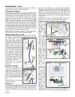
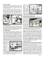
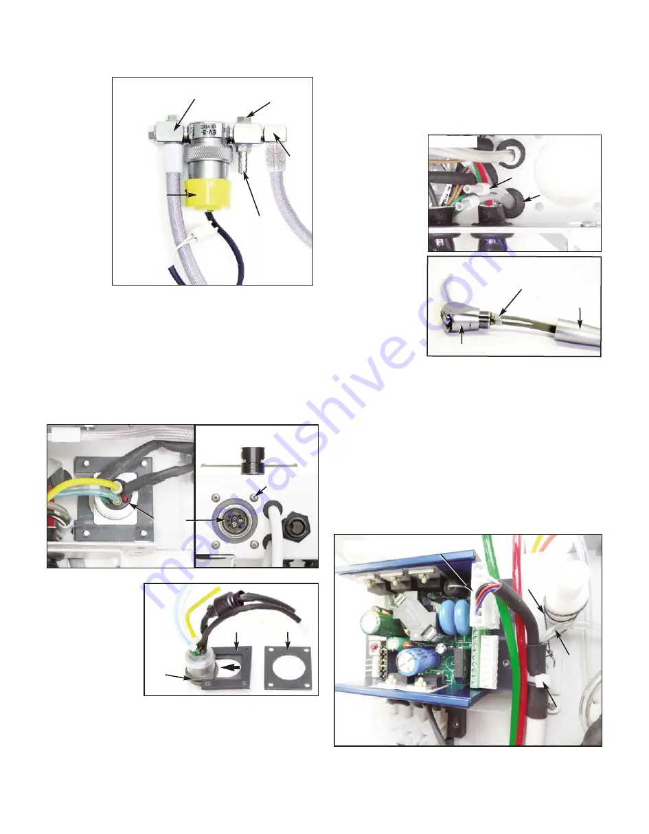
SCALER WAND
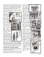
The Scaler Wand (part of PN 730691) is attached inside the
Air & Electric Module (Fig. 60). Unplug the Scaler Connector
from the scaler module. Cut the Cable Tie around the Scaler
cord. Remove the Scaler Tube from the manifold. Cut the
Anchor Line wrapped around the standoff.
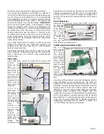
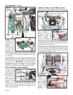
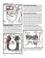
At the workbench, disconnect the remaining two sleeve
clamps and
hoses from
the
two
Fittings (PN
730139) (Fig.
52). Use a
1/4"
thin
open-ended
wrench
to
remove the 2
b a r b e d
Fittings (PN
7 3 0 0 7 3 ) ,
three Plugs
(PN 730072),
and
eight
n y l o n
Gaskets (PN
730074). Use
a 3/8" open-ended wrench to remove the two cross Fittings
(PN 730139) and 90 degree angle fitting (PN 750537).
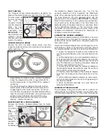
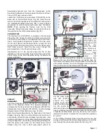
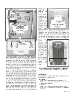
ELECTRIC MOTOR RECEPTACLE
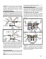
The Electric Motor Receptacle Assembly (PN 330598) is
mounted onto the bottom panel of the Air & Electric Module
(Fig. 53a). Locate the 4 Mounting Screws (PN 510160) on
the bottom of the Module and remove them using a 5/64"
Allen Wrench (Fig. 53b). Move the entire Receptacle
Assembly to the workbench for further disassembly, if
necessary.
NOTE:
At
the
workbench,
take
note
how
the
Adapter Plate (PN
462069) slides into
the slot on the
Receptacle. Also
note the hole-
orientation of the
Spacer
(PN
462135), with the Adapter Plate and Receptacle (Fig. 57).
Page 11
Figure 57
Figure 58
SPACER
MTG.
SLOT IN
RECEPTACLE
GROMMET
ADAPTER
Figure 59
TUBING
SLEEVE CLAMPS
(X2)
HANDLE
SYRINGE TUBING &
SLEEVE CLAMPS
HEAD
Figure 52
BARBED
FITTINGS
PN 730073
3-WAY
VALVE
CROSS
FITTINGS
PN 730139
PLUGS
PN 730073
PN 730537
Figure 53b
MOUNTING SCREWS
(X4)
MOTOR
RECEPTACLE
ASSEMBLY
Figure 53a
Figure 60
ANCHOR
LINE
CABLE TIE
SCALER
TUBE
SCALER
CONNECTOR

