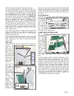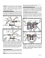
5/64" Allen wrench to remove the two Screws (PN 510720)
that mount the Spacer (PN 462034) to the Wall.
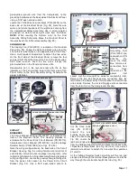
AIR BOTTLE ASSEMBLY
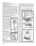
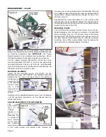
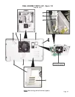
The Air Bottle Assembly is located inside the Transport III
Case, in the upper right-hand corner of the top compartment
(Fig. 64a). Turn the unit off and purge any residual pressure
left in the System (depress the Syringe air button to release
all air pressure). Unscrew the Air Bottle (PN 730657) from its
Lid (PN 462007) and set Bottle aside for reassembly later.
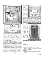
Cut the cable tie around the two gray tubes (PN AA-95G)
running to the Air Bottle Assembly (see Fig. 64b). Use a
Phillips screwdriver to remove the top mounting Screw (PN
510545) which threads into the Assembly Bracket (PN
462006), through the top of the Case. Then, use a 3/32"
Allen wrench to remove the other mounting Screw (PN
510309), which is accessed from the inside of the case.
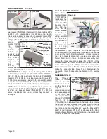
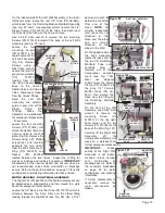
Carefully pull the Assembly
out of the Case to access
its tubing (Fig. 65). At the
Bottle Lid, remove the
Sleeve
Clamp
(PN
730095) and Tube (PN AA-
95G) that runs from the
Compressor
Assembly
(see Fig. 65). At the Filter
(PN 730495), locate the
Tube going to the
Bulkhead Manifold and use
a 7/16" open-end wrench
to remove it from the
straight Fitting on the Filter.
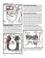
Move the Bracket
subassembly to the
workbench. Use a
3/32" Allen wrench to
remove the two
mounting Screws (PN
510404) for the Lid
and the two Screws
(PN 510309) for the
Filter (see Fig. 66).
Inspect and replace
the two Bumper Pads
(PN 850067) if necessary. Clean or replace Filter (PN
730495) as necessary. Check Bottle Gasket (PN 730473)
located inside the Lid (Fig. 65) for wear/leakage and replace
as necessary.
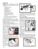
Anchor Line from the hold-down Nut with a 5/16" open-
ended wrench (see Fig. 53a). Pull the Scaler Wand cord
down through the grommet in the bottom panel of the Air &
Electric Module. Remove Scaler Wand.
IMPORTANT:
The
Scaler Wand is not a customer-serviceable item. Return the
Wand to Aseptico if repairs are required.
Reassemble the Scaler Wand in the reverse order, adjusting
the length of the Wand cord to hang suspended off the floor
and then trimming the excess cord and/or water line. Wrap
the cable tie around the scaler cord, just above the grommet
in the bottom panel of the Air & Electric Modulet. Ensure that
the tie is not over-tightened and does not restrict the flow of
water. Attach the anchor line to the hold-down nut. Attach the
green, white, and black wires from the Wand to the matching
colored wires on the 4-position terminal block. Check to
ensure that scaler water flow is appropriate.
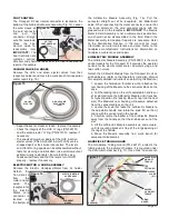
FOOTSWITCH CONNECTOR
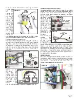
The Footswitch Connector (PN 860212) is located on the
bottom panel of the Air & Electric Module. Use a 13/16"
open-ended wrench
to remove mounting
nut on outboard side
of bottom panel (Fig.
61). (
NOTE:
Take
care to protect the
panel
against
scratches
when
removing nut.) Push
Connector inward
through 'D' shaped
cutout in bottom
panel of the Air &
Electric
Module.
Note
that
the
keyway on the
threaded Connector
is pointing toward
the right-hand side.
Remove
entire
Connector and wire
harness assembly
and set aside for reassembly later. (
NOTE:
During
reassembly, ensure that the rubber gasket that is supplied
with the Connector (see Fig. 62) is positioned on the inboard
side of bottom panel.
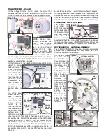
AIR/ELECTRIC MODULE LOCK-KNOB & HANDLE
The Air/Electric Module Locking
Knob and Handle are located on the
Front Wall (Fig. 63). If the Handle
(PN 462031) needs to be removed,
use a 5/64" Allen wrench to remove
its two mounting Screws (PN
510037). The Locking Knob consists
of six different parts: Use a 1/8"
Allen wrench to remove the
large shoulder Screw (PN
510767) and Spring (PN
510765) that attach the Lock
Knob (PN 462033). Then, use a
Page 12
HANDLE
Figure 63
Figure 61
MOUNTING
NUT
FOOTSWITCH
CONNECTOR
KEYWAY
Figure 62
'D' SHAPED
CUTOUT
FOOTSWITCH
CONNECTOR
W/WIRE
HARNESS
RUBBER
GASKET
LOCK
KNOB
SHOULDER
SCREW
SPRING
KNOB
SPACER
TUBE
FROM
COMPRESSOR
ASSEMBLY
Figure 65
TUBE TO
BULKHEAD MANIFOLD
1/4" SLEEVE
CLAMPS
(X2)
BOTTLE CAP
MOUNTING SCREWS
BUMPER
PAD (X2)
Figure 66
FILTER
MOUNTING SCREWS
LID GASKET
Figure 64b
Figure 64a
AIR
BOTTLE
ASSEMBLY
CABLE
TIE
FILTER
ASSY
MOUNTING
SCREW
MOUNTING
SCREW
DISASSEMBLY - Cont'd

