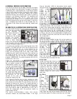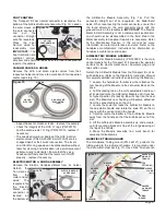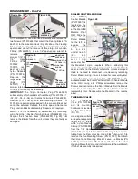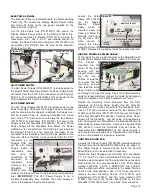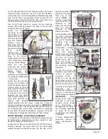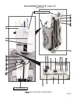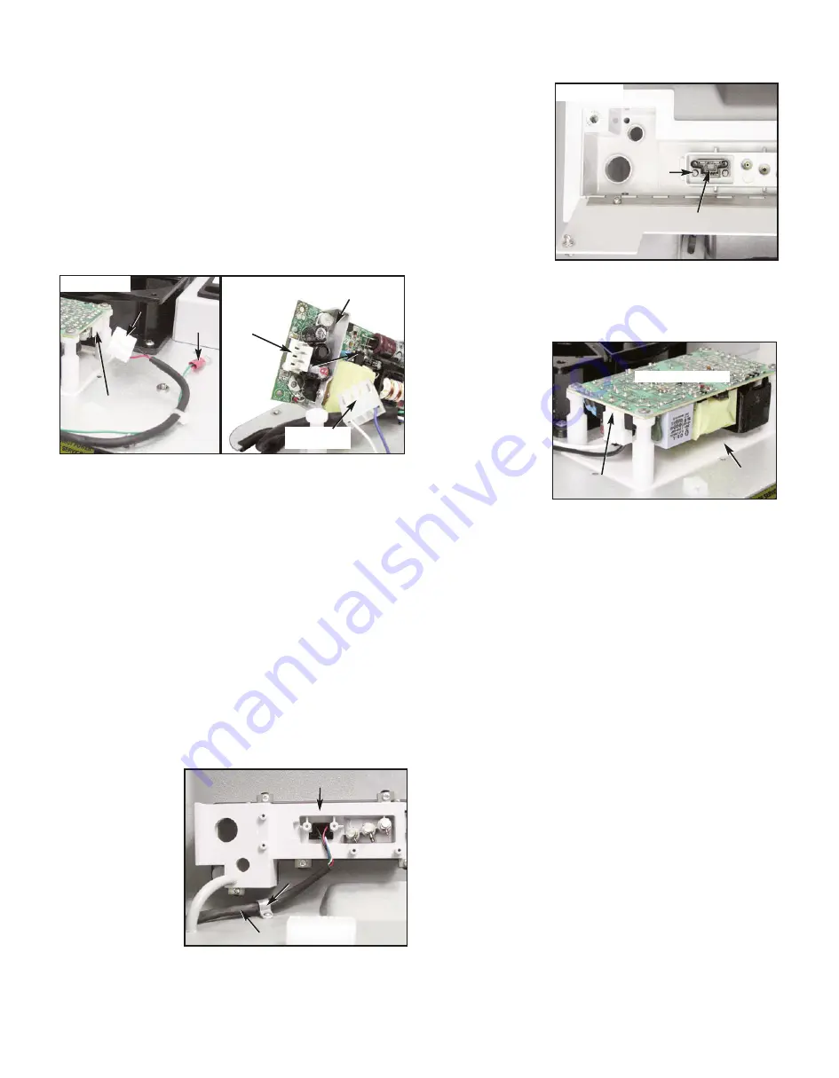
Locate the Cable
Clamp (PN 510410)
for the Display
Module
Power
Cable, which is
mounted inside the
Case, just below the
Manifold Insert (see
Fig. 82). Use a 3/32"
Allen wrench to
remove the Clamp
mounting Screw (PN
510404). Remove Clamp and set aside for reassembly later.
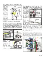
DISPLAY MODULE POWER CABLE
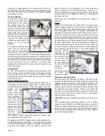
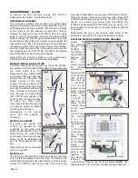
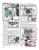
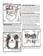
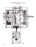
At the top of the case, open the door to the Manifold Insert
and locate the Display Module Power Cable 12-Pin Socket.
This Socket is
mounted into the
center of the Insert
housing with two
integral screws (see
Fig. 83). Use a
Phillips screwdriver
to remove the two
mounting screws,
then feed the entire
Power Cable up and
out through the Insert housing. Place the Cable Assembly
aside for reassembly later. Inspect the Cable for damage or
faults and replace entire Cable if problems are found.
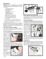
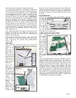
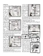
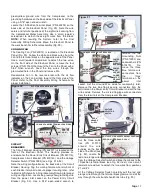
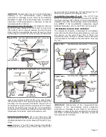
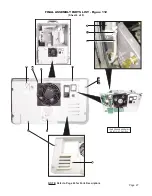
Detach the remaining 2-wire connector from the 'CN1'
receptacle on the 48V Power Supply (Fig 84). Note the
orientation of the 2-wire connector to the receptacle latch.
Use a 1/16" Allen wrench to remove the four Screws (PN
510016) and Washers (PN 510573) that secure the Supply
to the four Standoffs (PN 462244). Carefully lift the Power
Supply off the Standoffs. and set aside until reassembly
later. Unscrew the four Standoffs on the Electrical Panel and
place aside for reassembly later. Remove the Insulator Pad
(PN 462081) under the Standoffs and set aside for
reassembly later.
IMPORTANT:
The 48V Power Supply is
not a customer-serviceable item. Replace the entire Supply
or return it to Aseptico if repairs are required.
CONTROL BOARD PCB
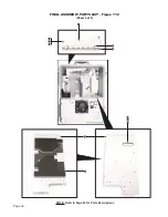
A smaller 24V Power Supply (PN 840093) provides power to
the Electronic Control Board (PN 330604) (Fig. 85, page 16).
This Power Supply is mounted to the top of the Control
Board PCB and can be detached if necessary.
Detach the three flag-type wire terminals from connectors
'T1', 'T2', and 'T3' on the Control Board PCB (see Fig. 86).
Note the color-arrangement of the wires and the connectors.
Next, detach the four wire connectors at the PCB sockets
marked 'J_WASTE', 'J_SOL', 'J_PRESS SW', and 'J_LEDS'.
Note the alignment of the connectors to the socket latches,
and the wire color positions. Use a 1/16" Allen wrench to
remove the four mounting Screws (PN 510016), split
lockwashers (PN 510433), and flat nylon washers (PN
510657) that mount the Control Board PCB to the four
Standoffs (PN 510760). Next, use a 5/64" Allen wrench to
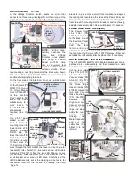
ELECTRICAL PANEL
The Electrical Panel is located beneath the Motor Housing
Cover (Fig. 79). Locate the Display Module Power Cable
and follow it's leads to the two power supplies on the
Electrical Panel (Fig. 80).
Cut the three Cable Ties (PN 510137) that secure the
Display Module Power Cable to the Electrical Panel (Fig.
80). Leave the three Tie Mounts (PN 510179) in place, for
reassembly later. Use a 5/16" open-ended wrench to
remove the Power Cable Grounding Nut (PN 510293) and
Lockwasher (PN 510419) from the stud on the Electrical
Panel (see Fig. 80).
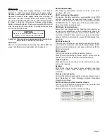
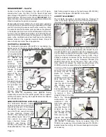
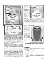
48V POWER SUPPLY
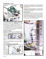
The 48V Power Supply (PN 840087-01) provides power to
the Electric Motor Assembly. Detach the Power Cable 2-wire
connector from the 'CN2" 4-pin receptacle on the Supply's
PCB (Fig. 81a). Note the orientation of the connector to the
PCB receptacle latch and pin-position of red wire.
24V POWER SUPPLY
The 24V Power Supply (PN 840120) provides power to the
Scaler Assembly. To access the Supply's power connector,
which is situated on the Supply's underside, the Supply must
first be removed from its mounting Standoffs and turned
over. Use a 1/16" Allen wrench to remove the four Screws
(PN 510016) and Washers (PN 510573) that secure the
Supply to the four Standoffs (PN 462244). Carefully lift the
Power Supply off the Standoffs, then detach the Power
Cable's 2-wire connector from the 'CN2' 4-pin receptacle on
the Supply's PCB (Fig. 81b). Note the orientation of the
connector to the receptacle latch and the pin-position of the
blue wire. Detach the other 2-wire connector from the 'CN1'
receptacle on the
Supply's PCB, then
set the 24V Power
Supply aside for
reassembly later.
Also
note
the
orientation of this
connector to its
receptacle
latch.
Unscrew the four
Standoffs
(PN
462244) from their
studs on the Electrical Panel and place aside for reassembly
later.
IMPORTANT:
The 24V Power Supply is not a
customer-serviceable item. Replace the entire Supply or
return it to Aseptico if repairs are required.
Page 15
Figure 82
MANIFOLD INSERT
CABLE CLAMP
DISPLAY MODULE POWER CABLE
Figure 81b
Figure 81a
48V POWER SUPPLY
4-PIN RECEPTACLE
2-WIRE
CONNECTOR
GROUND
WIRE RECEPTACLE
2-WIRE
CONNECTOR
24V POWER SUPPLY
(Underside)
Figure 83
MANIFOLD INSERT
(INSERT
DOOR)
DISPLAY MODULE POWER CABLE
12-PIN SOCKET
MTG.
SCREW
(X2)
48V POWER SUPPLY
Figure 84
'CN1'
RECEPTACLE
INSULATOR
PAD

