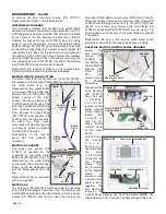
ELECTRICAL PANEL 10-POS TERMINAL BLOCK
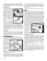
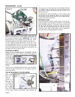
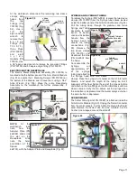
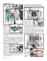
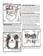
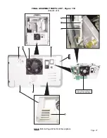
Rotate the Compressor Assembly so the Electrical Panel is
facing forward (Fig. 88). Locate the two red wire connectors
from the Unloader Solenoid
Cable
Assembly
(PN
875115) and the two red
connectors
from
the
Pressure Control Switch
Cable
Assembly
(PN
875116) in the upper right-
hand corner of the Panel
(see Fig. 88 inset). Disconnect all four wire connectors. Cut
all cable ties located on the front of the Electrical Panel and
along the edge of the Cooling Fan.
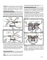
Locate the four mounting Screws (PN 510037) that attach
the Electrical Panel to the Compressor Assembly (see Fig.
88) and remove them using a 5/64" Allen wrench. Carefully
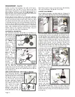
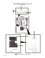
lower the top front edge of the Panel downward to expose
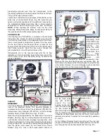
the back side of the Panel.(Fig. 89).
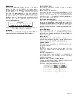
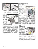
Locate
and
disconnect the
two pink female
wire connectors
from the Pressure
Control Switch
Cable Assembly.
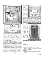
Locate
and
detach the
remove
the
mounting Screw
(PN 510160) that
attaches the the
Heatsink
(PN
462111) to the
PCB. Carefully lift
the Control Board
Assembly off the
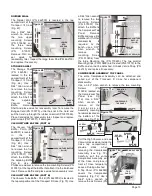
Standoffs and move to a workbench for further disassembly.
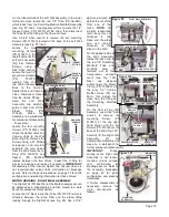
Use a 1/4" open-ended wrench to remove the four Standoffs
then remove the Insulator Pad (PN 462080) and set aside
for reuse later.
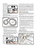
At the workbench, cut and remove the Cable Tie (PN
510628) that straps the Power Supply to the Control Board
PCB. Lift the Power Supply straight up and off the mounting
pins on the PCB .
IMPORTANT:
The Power Supply and
Control Board PCB assemblies are not customer
serviceable. If repairs are required to either assembly,
replace the entire item or return it to Aseptico for service.
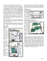
WASTE CONNECTOR CABLE ASSEMBLY
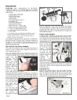
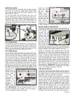
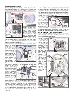
Locate the Waste
Connector Cable
Assembly Bracket
(Part of Cable Assy
PN 875114) (Fig.
87). Cut the two
Cable Ties (PN
510137) that bundle
the wiring to the
Control
Board
Assembly (see Fig. 86 above). Use a 5/64" Allen wrench to
remove the two mounting Screws (PN 510037) for the
Bracket. Remove Bracket and Cable Assembly and set
aside for reassembly later.
Page 16
DISASSEMBLY - Cont’d
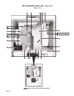
Figure 87
WASTE
CONNECTOR
BRACKET
Figure 88
Figure 86
INSULATOR
PAD
'J_WASTE'
CONNECTOR
HEATSINK
'J_SOL'
CONNECTOR
'J_PRESS_SW'
CONNECTOR
'J_LEDS'
CONNECTOR
'T3'
'T1'
'T2'
(24V PWR
SUPPLY)
STANDOFF
(X4)
CONTROL
BOARD
PCB
CONTROL
BOARD
PCB
MOUNTING
PINS (X4)
24V POWER SUPPLY
CABLE
TIE
CABLE TIE (X2)
MTG SCREW (X2)
CABLE
TIES
(X8)
MOUNTING
SCREWS (X4)
(ELECTRICAL PANEL ROTATED FORWARD)
Figure 89
(TAG WIRE
CONNECTIONS)
PRESSURE CONTROL
SWITCH CABLE
CONNECTORS
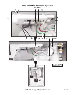
GROUND WIRE
MTG HARDWARE
COMPRESSOR
GROUND WIRE
COMPRESSOR
MOTOR WIRING
TERMINAL
BLOCK
Figure 85

