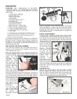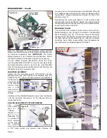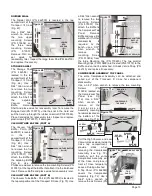
breakers in place. Use a small flat screwdriver to depress
the locking tabs located on the sides of the Power Entry and
Compressor Breakers and pull each Breaker out through the
front side of the Housing. Set the Breakers and the Housing
aside for reassembly later. Replace Breakers if necessary.
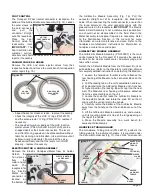
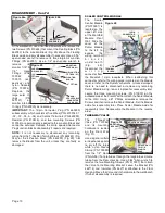
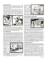
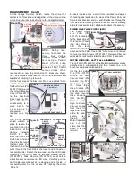
POWER INLET LINE FILTER (EMI)
The Power Inlet
Line Filter (PN
840121) is mounted
to the back side of
the Electrical Panel
(Fig. 96). Discon-
nect
the
four
terminals/wires
attached to the Filter. Use a 5/64" Allen wrench to remove
the two mounting Screws (PN 510037). Remove Filter and
set aside for reassembly later. Replace Filter if necessary.
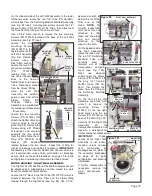
MOTOR HOUSING - LEFT WALL ASSEMBLY
The Left Wall (PN 462010) of the Motor/Compressor can be
detached as a subassembly and then moved to a work
bench for component disassembly.
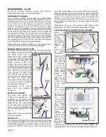
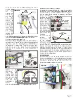
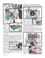
Cut the four Cable
Ties (PN 510137)
around the Low
Vacuum Hose (PN
AA-86G) (Fig. 97).
Use pliers to pry off
the three large
Hose Clamps (PN
510425) around the
two High Vacuum
Hose sections
(PN AA-259).
Remove
the
High and Low
Vacuum Hoses
from their fit-
tings and place
aside for reas-
sembly later.
Unplug
the
Motor Capacitor
and cut the
cable ties that
attach it to the
left wall.
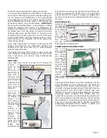
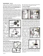
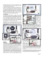
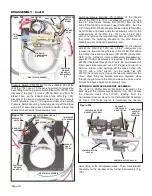
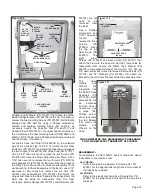
At the Voltage Selector Switch, locate the crimp that
connects the three blue wires together. At the crimp, cut the
single blue wire that leads directly to the Voltage Selector.
NOTE:
During reas-
sembly, reconnect the
three blue Voltage
Selector wires shown
here using a Panduit
Model CT-1551 crimp
tool, or equivalent tool
capable of #22-10 AWG
contour crimps. When
reconnecting a new flag terminal to the black wire shown
here, use a Molex Model 640014100 tool, or equivalent tool
capable of crimping flag terminals.
On the front side of the Electrical Panel, use a 5/64" Allen
wrench to remove
the four Screws (PN
510037) that mount
the Circuit Breaker
Cover (PN 462017)
to the Electrical
Panel (see Fig. 94).
Move the Cover
subassembly to a
work bench for
c o m p o n e n t
disassembly
if
required (see Fig.
95).
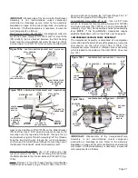
Use a 9/16" open-
ended wrench or
pliers to loosen the
mounting nut on the
inboard side of the
Voltage Selector
Switch (Fig. 95).
Back the nut off the
Switch by hand and
then slide the nut off
the four wires. Pull
the Switch and four
wires through the front side of the Cover and set aside for
reassembly later. Detach the two leads on the LED Cable
Assembly (PN 875117) from the two LED Diffuser Lenses
(PN 850078). Slide Grommet (PN 870185) out of hole in
circuit breaker cover around LED wires. Carefully pull the
LED Cable Assembly out of the Housing and set aside for
reassembly later. Cut the silicone RTV locking the circuit
Page 18
DISASSEMBLY - Cont’d
Figure 93
RED &
ORANGE
WIRES
CUT THIS
WIRE HERE
Figure 94
CIRCUIT BREAKER COVER
MOUNTING SCREWS
(X2 Each Side)
REMOVE THIS FLAG TERMINAL
VOLTAGE
SELECTOR
SWITCH
Figure 95
VOLTAGE
SWITCH
MOUNTING
NUT
LOCKING TAB (Typical)
LED
DIFFUSER
LENS (X2)
LED CABLE ASSY
COMPRESSOR
CIRCUIT
BREAKER
POWER
ENTRY
CIRCUIT
BREAKER
GROMMET
Figure 96
EMI FILTER
MOUNTING
SCREWS (X2)
Figure 97
CABLE
TIES
(X4)
MOTOR
CAPACITOR
HIGH
VACUUM
HOSE
LEFT WALL ASSEMBLY
HOSE
CLAMPS
(X3)
LOW
VACUUM
HOSE
VACUUM
SPLITTER
MTG
SCREWS
(X2)
SWITCHING
MODULE MANIFOLD TUBE
SLEEVE
CLAMP
VACUUM
VALVE
LOW
VAC
HOSE

