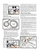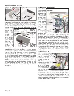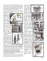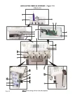
open-end wrench to
detach the nut at the
filter end of the
Hose.
NOTE:
To
simplify reassembly
later, leave this nut
attached to this
Hose end; the other
end can remain
attached to the
elbow in the Wall.
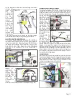
On the opposite side of
the Wall Assembly,
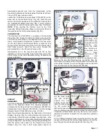
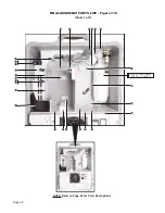
locate the loose end of
the red 1/8" Switching
Manifold Tube and
carefully
draw
it
forward, out of the
Compressor compart-
ment (see Fig. 100).
Next, use diagonal
cutters to pry the Sleeve
Clamp (PN 730095) off
the gray 1/4" Venturi-
Muffler Hose (PN AA-
95G), then detach the
Hose from the fitting on
the Switching Manifold
Assembly.
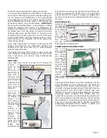
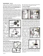
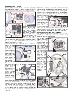
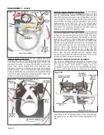
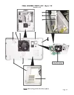
On the front of the Wall
Assembly, use a 5/64" Allen
wrench to remove the
mounting Screw (PN
510037) at the top right-
hand corner, and the two
Screws (PN 510160) at the
base of the Wall (Fig. 101).
Carefully lift the Right Wall
Assembly
off
the
Compressor Assembly and
move to a workbench for
further component disassembly.
IMPORTANT:
Disas-
sembly of the Right Wall
Assembly is not recom-
mended unless compo-
nent
malfunction
or
breakage occurs. Refer to
the assembly breakdown
on page 42 for parts
configuration and ordering
information.
If further disassembly is
necessary, remove the
main components as
follows:
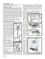
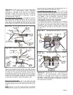
On the inboard side of the Left Wall Assembly, in the lower
left-hand corner, locate the red 1/8" Tube (PN AA-94R),
which leads from the Switching Module Manifold Assembly
(see Fig. 97 inset). Use diagonal cutters to work the 1/8"
Sleeve Clamp (PN 730015) off the Tube, then disconnect
the Tube from the fitting on the Vacuum Valve.
Use a 5/64" Allen wrench to remove the two mounting
Screws (PN 510160) located at the base of the Left Wall
Assembly (see Fig. 97 inset).
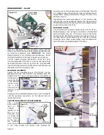
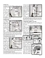
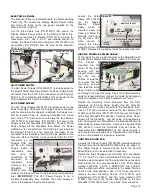
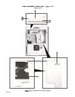
Locate the two
mounting Screws
(PN 510037) in the
top left corner of the
Left Wall Assembly
(Fig. 98). Remove
Screws, using a
5/64" Allen wrench.
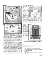
Locate the two 1/2"
gray vacuum Hoses
(PN
730373)
leading from the
two Venturi Assem-
blies to the Vacuum
Splitter Valve and Vacuum
Valve. Disconnect Hoses
from the Valves' fittings.
Hold the Left Wall
Assembly and carefully
guide it over and off the
Elbow
Fitting
(PN
730484).
Move
the
Assembly to a workbench
for component disassembly
- if necessary.
Locate the four mounting
Screws (PN 510618) that
attach the Splitter Valve and
Vacuum Valve to the Wall
plate (Fig. 98). Remove the
Screws using a #1 Phillips
screwdriver and carefully
separate the two Valves
from the Wall. Note the O-
Ring (PN 520079) and
Spacer (PN 462086)
located between the two Valves. Inspect the O-Ring for
cracks or leakage and replace if necessary.
IMPORTANT:
Disassembly of the Vacuum Splitter and Vacuum Valves is
not recommended unless Valve malfunction or breakage
occurs. Refer to the parts breakdown on page 37 for parts
configuration and ordering information for these Valves.
MOTOR HOUSING - RIGHT WALL ASSEMBLY
The Right Wall (PN 462016) of the Motor/Compressor can
be detached as a subassembly and then moved to a work
bench for component disassembly.
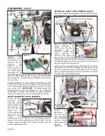
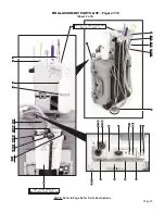
Locate the 1/4" black inline filter Tube (PN 730130) which is
attached between the Inline Filter and the elbow fitting
leading through the Right Wall (see Fig. 99). Use a 7/16"
Page 19
Figure 98
VACUUM
SPLITTER
VALVE
MOUNTING
SCREWS
(X2)
ELBOW
FITTING
VACUUM
VALVE
VACUUM HOSES (X2)
COUPLER
SPACER
O-RING
MOUNTING
SCREWS
(X4)
SPLITTER
VALVE
VACUUM
VALVE
Figure 99
RIGHT WALL ASSEMBLY
MOUNTING
SCREWS (X2)
Figure 101
MOUNTING
SCREW (X1)
INLINE FILTER HOSE
INLINE FILTER
(DETACH
THIS
END)
Figure 100
RIGHT WALL ASSEMBLY
SWITCHING
MODULE
MANIFOLD
VENTURI
MUFFLER ASSY
(PULL TUBE FORWARD)
(DETACH
THIS END)
VENTURI MUFFLER
HOSE

