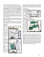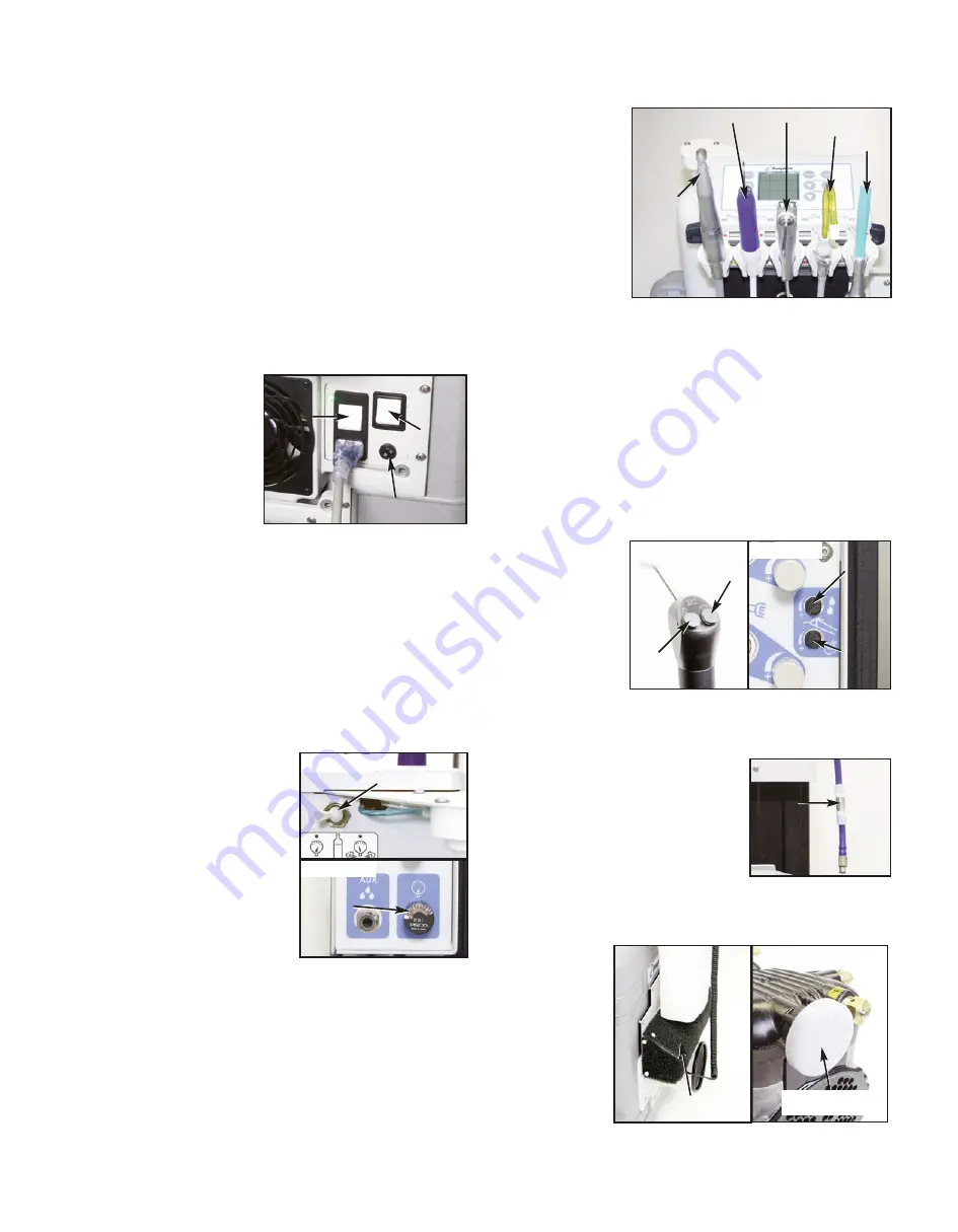
Vacuum Evacuator (HVE) or low-volume saliva ejector
instruments (Fig. 3) are removed from their holders or if they
aren't
properly
seated in their
holders, the com-
pressor will run
continuously, even
when the system
pressure is fully
pressurized. If the
HVE and saliva
ejector instruments
are seated in their
holders properly but the compressor fails to turn off, turn the
unit's power switch OFF and check for air leaks in the
system. If the system pressure gauge is showing pressure,
the leaking sound should be detectable. Use your ear, or
place a tube to your ear like a stethoscope, to locate the
source of the leak. If a leak can't be heard from any air lines
or fittings, check the air and water bottles for tightness and
the condition of their seals, and check the three O-rings from
the junction block.
Air/Water Syringe
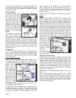
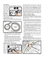
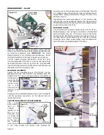
Check the 3-Way Air/Water Syringe (Fig. 4a) by depressing
the air and water syringe buttons individually then both
simultaneously for air/water mist. This mist can be adjusted
with the two syringe
flow control knobs
located on the
manifold control
panel (see Fig. 4b).
The top knob
adjusts the water
flow and the bottom
knob adusts the air
flow. Turn the knobs clockwise to decrease the flow or
counterclockwise to increase the flow.
Water Filter
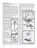
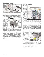
Inspect the water filter (Fig. 5) on the
end of the water pick-up tube that
protrudes into the water supply bottle.
If the filter becomes clogged and
restricts the water flow, it needs to be
cleaned by reverse flushing, or
replaced. CAUTION: Do not run saline
solutions through the water system -- saline will rust the
water filter.
Air Filters
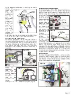
The
system
provides a dual
air
filtration
system.
The
primary
filter
(Fig. 5a) is
installed into the
door frame on
the case lid and
is used in dusty
environments. It
uses a foam filter that can be detached and cleaned. Simply
pull the foam pad off the frame studs and clean with soap
GENERAL SERVICE INFORMATION
This service and parts manual offers information and parts
lists not available in the AEU-525CF Transport III Operation
and Maintenance Instruction Manual. It will help you better
understand the operation of the Transport III system, thereby
reducing service time. A Schematic Diagram Set includes
assembly drawings with individual part numbers, plumbing
diagrams, and electrical schematics. The plumbing and
electrical diagrams show all air, water, and wiring
components as installed in the unit. Individual parts are also
listed and referenced to Figures with callouts in the Parts
Lists. A Replacement Parts List is also included. Use the
information in the Parts Lists when ordering replacement
parts.
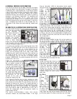
INSPECTION & OPERATION VERIFICATION
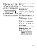
To verify that the Transport III unit is functioning properly, first
follow the Setup procedure
in the Operation and
Maintenance Manual or in
the 525 Setup Video
presented on the Aseptico
website. The System is
designed to operate from
110V or 230V 50/60Hz
power. A manually operated
switch located next to the power inlet cord, allows the user
to select the proper voltage (Fig. 1).
Turn both rocker switches on the motor housing to the ‘ON’
position. The left-hand switch turns the unit power On/Off.
The right-hand switch acts as a circuit breaker for the
compressor. Electrical overloads will trip both switches.
Simply turn the switches back On to reset. Green LED’s
adjacent to each switch illuminate when the switches are
On. NOTE: When the unit is in use, it’s compressor motor
will occasionally turn On and Off, to maintain proper
pressure. IMPORTANT: The switch should be left in the On
position when not in use.
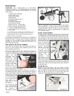
Toggle the water-bottle purge
switch located on the back side of
the air/ electric module to the
“PRESSURE” position (Fig. 2a).
Turn the main power switch, to
the ON position. The compressor
pump should pressurize the air
and water bottles and maintain
the system operating pressure at
45-55 PSI (3.10-3.79 bar). Check
the pressure on the gauge
located on the side of the
air/electric module (Fig. 2b).
The Transport III System uses a single compressor motor
with a split head. The split head provides pressure on one
side and vacuum on the other. The vacuum side uses venturi
boosters to increase the vacuum. The system pressure is
regulated by a switch located on the right wall of the motor
housing assembly. This switch activates the compressor
when the pressure drops to approximately 45 PSI, and it
stops the compressor when the pressure builds to
approximately 55 PSI.
The electric motor/handpiece, scaler, and vacuum
instrument holders are air-activated holders. If the High
Page 1
VOLTAGE SELECTOR
SWITCH
POWER
ON/OFF
COMPRESSOR
CIRCUIT
BREAKER
Figure 1
Figure 2a
Figure 2b
WATER BOTTLE
PURGE SWITCH
PRESSURE
GAUGE
HVE
ELECTRIC
HANDPIECE
SCALER
SALIVA
EJECTOR
SYRINGE
Figure 3
Figure 4a
Figure 4b
SYRINGE
AIR
ADJUST
AIR
WATER
SYRINGE
WATER
ADJUST
Figure 5
Filter
DETACHABLE
AIR FILTER
Figure 5a
Figure 5b
COMPRESSOR
AIR FILTER

