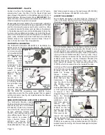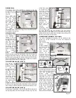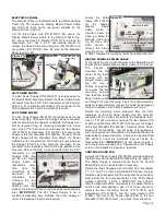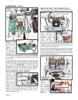
Page 2
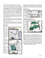
and water or compressed air. The secondary air filter is a
cannister-type filter that threads into the compressor head
(Fig. 5b). This filter should be replaced if it becomes clogged
and restricts air flow.
Vacuum System
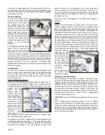
To check the function of the vacuum system, first allow the
system to reach full pressure.
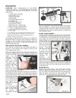
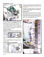
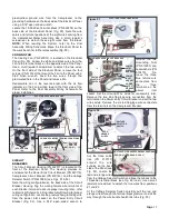
Check that all four tubes to
the waste tank are fully
seated and locked into their
fittings on the top of the waste
tank (Fig. 6a). Ensure that the
waste tank level sensor is
plugged into the connector on
the unit’s compressor housing
(Fig. 6b). The system will not
activate the compressor if this
sensor is not connected
properly.
Fill a container with one liter of
water. Turn the valve on the
low vacuum saliva ejector
instrument to the OFF position and submerge the HVE
instrument into the container. It should take approximately 6
seconds to extract the liter of water from the container using
the HVE. Refill the liter of water and turn the HVE instrument
OFF and the saliva ejector to ON, then submerge the saliva
ejector instrument into the container. It should take
approximately 42 seconds to remove one liter of water using
the saliva ejector.
Instruments:
To check the functions of the electric motor/handpiece and
scaler, remove each instrument from its respective holder
one at a time (see Fig. 3), and test the instrument, with
coolant water and/or air flow. Both instruments are activated
by the foot control.
Electric Motor/Handpiece
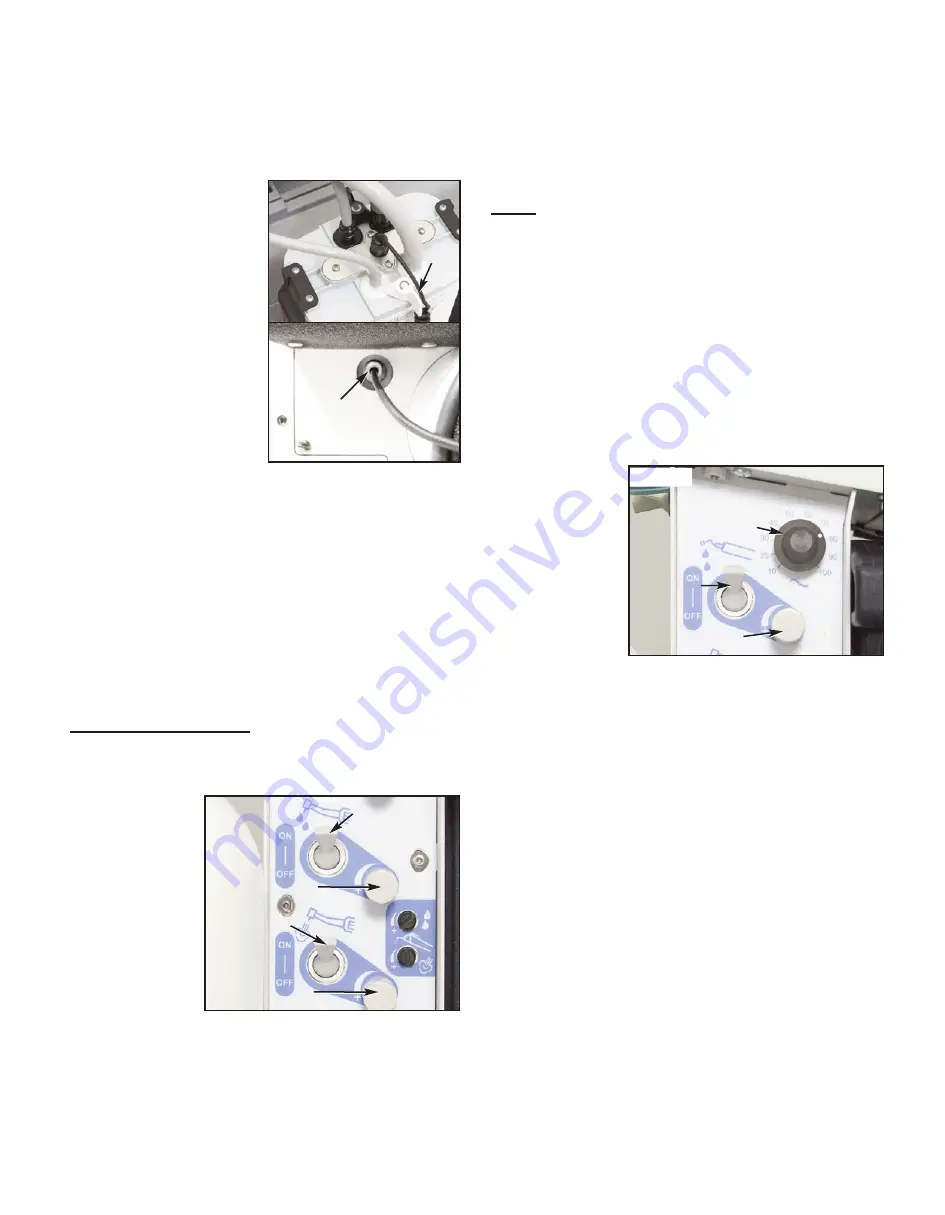
Remove the electric motor/handpiece from its holder (Fig. 3).
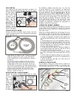
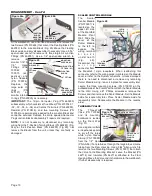
A handpiece water ON/OFF toggle valve is located on the
manifold control panel (Fig. 7). Place this toggle in the “ON”
position and de-
press the foot
pedal. Ensure that
coolant water flows
to the handpiece. A
water flow adjust-
ment valve is also
provided to control
the volume of water
going to the hand-
piece. This valve is
located next to the
ON/OFF
toggle
valve (Fig. 7). Turn
this adjustment valve counterclock-wise to increase flow,
then clockwise to decrease flow.
A handpiece air ON/OFF toggle valve is also located on the
manifold control panel (see Fig. 7). This valve allows coolant
air to flow to the electric handpiece. Depress the foot pedal
and place this toggle in the “ON” position. Ensure that
coolant air flows to the handpiece. An air flow adjustment
valve is located next to this ON/OFF toggle valve (Fig. 7).
Turn this adjustment valve counterclockwise to increase the
volume of air to the handpiece, then turn it clockwise to
decrease the flow.
Return the electric handpiece to its holder when testing is
complete.
Scaler
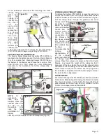
Remove the Scaler from its holder (Fig. 3). A scaler water
ON/OFF toggle switch is located on the manifold control
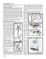
panel, just below the ultrasonic adjustment knob (Fig. 8).
Place this toggle switch in the “ON” position and depress the
foot pedal. Ensure that coolant water flows to the scaler. A
water flow adjustment valve is also provided to control the
volume of water going to the scaler. This valve is located
next to the On/OFF toggle switch. Turn this adjustment valve
counterclockwise to increase coolant flow, then clockwise to
decrease coolant flow. During normal operation, adjust this
valve until the water flow is no less than 20 ml/min at the tip.
A scaler ultrasonic setting control switch is also located on
the manifold control panel (Fig. 8). This switch adjusts the
ultrasonic intensity of the scaler. Turn the control knob
clockwise to max-
imum intensity, then
counterclock-wise
to minimum. When
scaling, follow the
tip manufacturer's
r e c o m m e n d e d
ultrasonic settings
for each tip.
Return the scaler to
its holder when
testing is complete.
Cleaning and Lubrication:
When servicing the Transport III system, the parts of any
component disassembled should be thoroughly cleaned and
inspected before reassembly. A hot detergent solution is an
effective cleaner on all non-electrical parts. Flush all non-
electrical parts with clear, hot water. Abrasive cleaners have
the potential to damage surface finishes and should be
avoided. Any wiping should be done with a soft lint-free cloth.
Electrical parts should be cleaned with an appropriate
electrical parts cleaner or air.
CAUTION
: Use only NON-foaming cleansers in the vaccum
lines.
Use a silicone base lubricating grease, such as Parker
Super O-Lube, PN 490138, to lubricate O-rings and seals in
the system. Before performing any reassembly of parts that
contain O-rings or seals, apply a light coat of silicone grease.
This will make installation easier and prevent the O-rings or
seals from being damaged.
Figure 6a
LEVEL
SENSOR
CORD
SENSOR CORD
CONNECTOR
(Below Air Filter)
Figure 6b
WASTE
TANK
HANDPIECE AIR
ADJUSTMENT VALVE
HANDPIECE AIR
ON/OFF VALVE
HANDPIECE WATER
ADJUSTMENT VALVE
HANDPIECE WATER
ON/OFF VALVE
SCALER
ULTRASONIC
CONTROL SWITCH
SCALER
COOLANT FLOW
ADJUSTMENT SWITCH
SCALER
COOLANT
ON/OFF SWITCH
Figure 7
Figure 8

