Page 47
AIR BOTTLE FILTER:
Routinely check the air bottle filter once a day for
condensation. To drain condensa-tion, place a towel or
container below the filter and use pliers to carefully loosen
the black knob on the bottom of the filter. IMPORTANT: To
open the drain, turn the black knob clockwise (follow arrow
on “DRAIN “ label); to close drain, turn the knob
counterclockwise. Do not overtighten.
WASTE SYSTEM CLEANING:
Empty and clean the waste system whenever the level alarm
occurs. Also empty and clean it routinely once a day or
before the unit is to be shipped or stored. Follow these steps:
1) Empty all waste from the waste container, including any solids
trapped in the HVE strainer in the waste container lid.
2) Prepare approximately 2/3 liter of 10% bleach/water solution in a
separate container. Submerge the end of the high-vacuum ejector
(HVE) into this bleach solution and pull no more than 1/3 liter of the
solution through the line into the waste container. Repeat this
process for the saliva ejector (low vacuum) line. IMPORTANT: The
solution will enter the waste container at a very high rate -- Care
must be taken not to overfill the container’s waste compartments.
3) Discard bleach solution. All components of the waste container,
including the lid assembly and waste container strainer, can be
safely rinsed with 10% bleach solution. (NOTE: Take care to ensure
that water is kept off the level-sensor electrical connector on the
case.) Rinse and dry tanks and the lid. If unit is to be shipped or
stored, hang vacuum lines vertically to allow any residual water to
drain before packing.
3-WAY AIR/WATER SYRINGE:
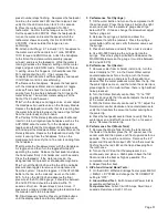
Depress the right button for air operation, and the left button
for water operation. Depressing both buttons will create a
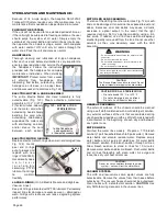
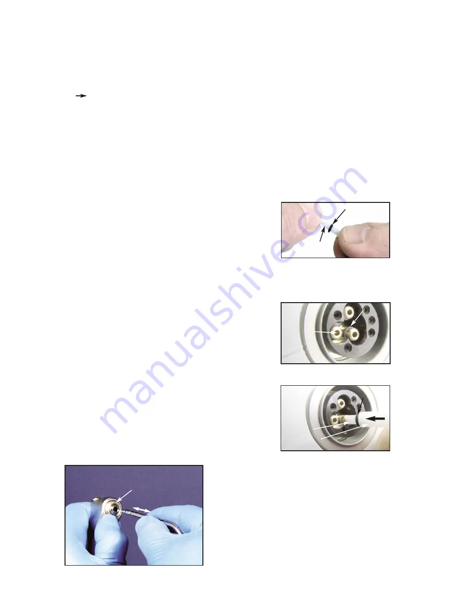
mist. The syringe features quick-change autoclavable tips: To
remove a tip, press on the locking collar surrounding the tip
socket and pull the used tip straight out of the socket (Fig.
125). To insert a new tip, press locking collar and push tip into
socket as far as it will go. Release ring and gently tug on tip
before using to ensure that tip is securely locked into socket.
Syringe Tip Sterilization:
1)
Remove contaminated syringe tip.
2)
Remove all visible signs of contamination before
autoclaving.
3)
Autoclave tip at 132° C (270° F) for ten minutes.
4)
Sterilize between each patient use.
NOTE:
Since only the tips can be autoclaved, it is
recommended that the air/water syringe be bagged with a
disposable, single-use plastic sleeve between each patient
use.
ULTRASONIC SCALER:
The scaler handpiece cover and scaler tips are fully
autoclavable. Disinfect and clean the cover and tips before
autoclaving. Autoclave at a maximum temperature of 135° C
(275° F) for 10 minutes or 120° C (248° F) for 20 minutes.
Wipe off the scaler handpiece and it’s silicone hose with a
soft cloth. Use a 45% isopropal and detergent solution.
DO
NOT IMMERSE
the handpiece in any fluid or spray any fluid
directly on the handpiece.
MOTOR/CORD RECEPTACLE O-RINGS:
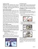
The O-rings (PN 520081) for the three water/air ports in the
motor/cord receptacle should be replaced if damaged or
worn. Use the provided O-ring installer pin and sleeve to
replace the O-rings:
1.
Remove old O-ring from water or air port fitting.
2.
Slide new O-ring over pointed end of installer pin, onto
the pin’s shank (see Figure 126).
3.
Insert pointed end of installer pin into open end of
installer sleeve until O-ring stops against end of tool.
4.
Position concave end of installer pin against end of
water/air port fitting (see Figure 127).
5.
Push installer sleeve inward, until new O-ring seats into
groove on fitting (see Figure 128).
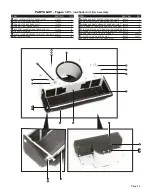
AIR FILTER ASSEMBLY:
The foam filter on the Air Filter Assembly should be cleaned
regularly if the AEU-525CF is used in a dusty environment.
Gently pull the foam sheet off the white mounting studs on
the Assembly frame and clean with soap and water or
compressed air. If washed, allow filter to dry before
operating unit.
FIG. 125
DEPRESS
LOCKING COLLAR
O-RING
INSTALLER
SLEEVE
FIG. 128
INSTALLER
PIN
O-RING
INSTALLER
PIN
FIG. 126
O-RING
FIG. 127
WATER/AIR
FITTING

