Page 5
FOOT CONTROL
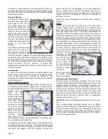
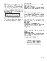
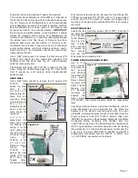
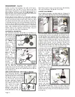
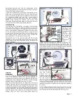
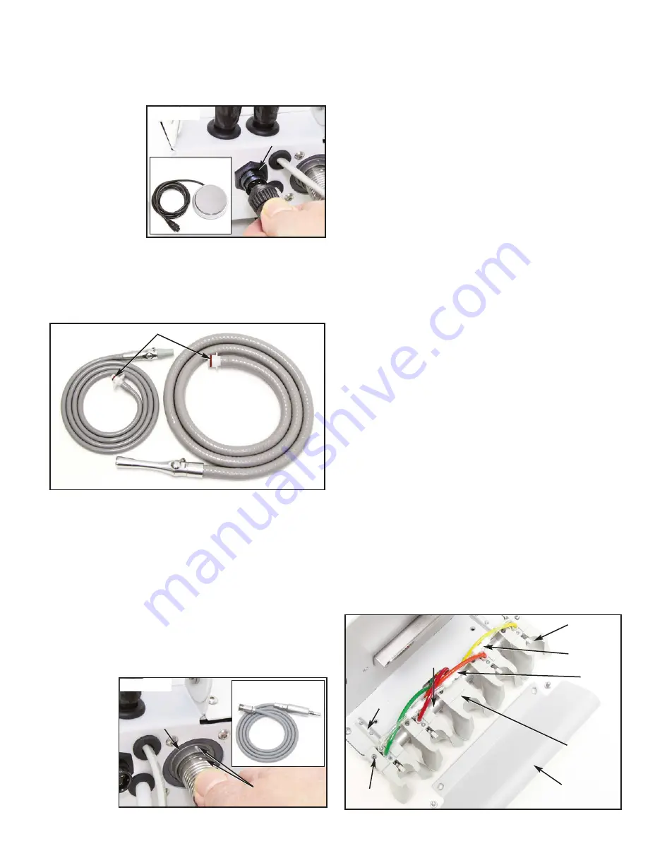
The Transport III Foot Control connector is located on the
bottom of the Air/Electric Module Assembly (Fig. 14). Loosen
the outer sleeve on
the cord connector
and
pull
the
connector straight
out of its receptacle.
Place the Foot
Control aside for
reassembly later.
IMPORTANT:
The
Foot Control is not a
customer service-
able item and should be replaced or returned to Aseptico for
repairs, if necessary.
VACUUM VALVES & HOSES
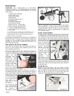
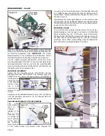
Remove the HVE and saliva ejector valves from their
respective holders and move to a work bench for inspection
and/or repair (Fig. 15):
• Inspect hoses for cracks or leaks - replace if necessary.
• Check the integrity of the HVE ‘O’ rings (PN 520101)
and the saliva ejector ‘O’ ring (PN 520100) - replace if
necessary.
• The anodized aluminum bodies of the HVE & saliva
ejector valves (PNs AA-35LAD & AA-37LAD) can be
snapped apart at their swivel connectors. The levers
and Viton® O-ring spools can be disassembled without
tools, for cleaning and lubrication. (Use small amount of
petroleum jelly to lubricate). Ensure that the valve
heads swivel freely and that the levers turn On/Off
properly - replace if necessary.
ELECTRIC MOTOR & CORD ASSEMBLY
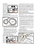
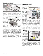
Remove the Electric Handpiece/Motor from its holder.
Detach the
h a n d p i e c e
from
the
motor and set
aside. The
receptacle for
the Electric
Motor cord
connector is
located on
the bottom of
the Air/Electric Module Assembly (Fig. 16). Pull the
connector straight out of its receptacle. Set Motor/Cord
aside. When reconnecting the motor connector, ensure that
the round dimple on the cord connector aligns with the
grooved mark on the receptacle.
IMPORTANT:
The Electric
Motor & Cord Assembly is not a customer-serviceable item
and should not be disassembled in the field. Return the
Motor Assembly to Aseptico if repairs are necessary. Refer
to the Sterilization Section in this manual for more
information on motor maintenance and care. Refer to the
handpiece manufacturers’ instructions for information on
handpiece maintenance and repair.
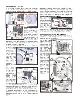
AIR/ELECTRIC MODULE ASSEMBLY
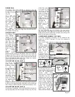
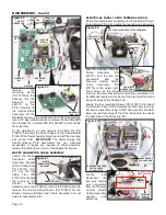
The Air/Electric Module Assembly (PN 330597) is the main
control module for the Transport III. It provides the operator
controls for the electric motor, scaler, air/water syringe, and
two suction valves.
Detach the Air/Electric Module from the Transport III unit as
outlined below: (Refer to the Operator’s Instruction Manual
for complete detailed instructions on detaching this Module.)
1. Loosen the hold-down thumbscrew that attaches the
rear housing of the Module to the connector block on the
case.
2. Pull the locking tab on the unit’s adjustable handle out
of its slot and raise the Air/Electric Module until it reaches
its highest positon (the locking tab will snap into the next
slot). The Module’s rear housing will become detached
from the connector block on the unit.
3. Locate the knob that locks the Air/Electric Module to
the adjustable handle and rotate the knob 90° so that it
aligns with the vertical slot in the handle.
4. Carefully rotate the bottom of the Air/Electric Module
away from the handle so that the knob backs out of the
slot.
5. Lift the Air/Electric Module assembly up and outward,
until its mounting bracket is free of the large opening at
the top of the handle.
6. Move the Module assembly to a work bench for
component disassembly.
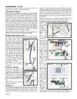
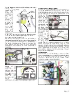
HANDPIECE TUBING GUARD
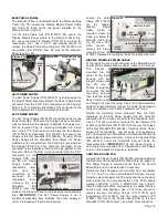
The Handpiece Tubing Guard (PN 462121) protects the
tubing going to the instrument holders. It is mounted under
the instrument holder bar (Fig. 17). Use a 5/64" Allen wrench
Figure 15
Figure 17
TEE
FITTING (X3)
TUBING
GUARD
HOLDER (X4)
w/ON-OFF
TOGGLE
O-RINGS
HIGH VOLUME
EVACUATOR
(HVE)
SALIVA
EJECTOR
ELECTRIC MOTOR
& CORD ASSY
Figure 16
RECEPTACLE
ALIGNMENT
MARKS
Figure 14
RECEPTACLE
AE-7PM
FOOT CONTROL
SET
SCREW(S)
SLEEVE
CLAMP
(X17)
HOLDER
w/o ON-OFF
TOGGLE
HOLDER
BAR
HOLDER
BAR
SUPPORT
(X2)

