Page 6
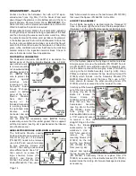
to remove the two mounting screws (PN 510037).
Reassemble the Guard in the reverse order.
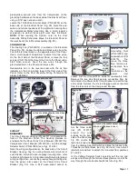
INSTRUMENT HOLDERS
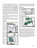
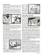
Two Instrument Holders (PN AA-59G) with on/off toggle
controls are located at each end of the Holder Bar (Fig. 17).
A fifth toggle-less instrument Holder (PN AA-68G) is located
at the center of the bar, between the other four Holders.
Remove the Sleeve Clamps (PN 730015) from the tubing
going to each of the Holders. Remove the colored tubing
and Tee Fittings (PN 730152) going to the Holders (take note
of the tubing configurations and colors to each Holder, for
reassembly later). Back out the setscrews on the bottom of
the Holder(s) with a 3/32" Allen wrench. Remove the Holders
from the Holder Bar. Use a 5/64” Allen wrench to remove the
two mounting screws (PN 510160) that attach the Holding
Bar (PN 462095) to the Holding Bar Supports.
Reassemble the Instrument Holders in the reverse order.
Refer to plumbing schematic for proper installation.
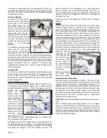
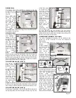
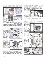
WATER FILTER & LUER FITTING
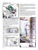
The Water Filter (PN 730326) and Luer Fitting (PN 730073)
are located in the blue tube (PN AA-95B) that protrudes into
the water bottle (Fig. 18).
Depressurize the water bottle
and remove it from its water cap.
Remove the Luer Fitting from the
bottom section of the tube.
Loosen the sleeve clamps (PN
730095) located at the top of the
blue tube and at both ends of the
Filter. Unscrew and remove the
Filter. Remove the three fittings
(PN 730073) and gaskets (PN
730074) from the tube sections.
To clean the Filter, inject
compressed air from the top end
to unplug its screen, or replace
the filter with a new one.
Reassemble in the reverse
order, with new gaskets if
necessary.
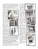
WATER CAP GASKET
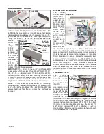
The water cap gasket (PN
730473) is located on the
underside of the white water
bottle cap (PN 462039) (Fig. 19).
Depressurize the water bottle
and remove it from its water cap.
Reach up into the white cap and
pull the black gasket from the
cap.
Reassemble in the reverse order
with a new gasket.
WATER CAP
The water cap (PN 462039) is attached under the right side
of the Air/Electric Module Top Panel (Fig. 19). Remove the
water bottle as previously described. Remove the two sleeve
clamps (PN 730015) from the two tubes, then detach the
blue tube (PN AA-94B) and clear tube (PN AA-94C) from the
fittings on the cap. Remove the three mounting screws (PN
510404) from the top of the panel (Fig. 18) with a 3/32" Allen
wrench and remove cap. Remove the two fittings (PN
730062) and gaskets (PN 730074) from the cap, using a 1/4"
open-ended wrench. Inspect and replace fittings or gaskets
if necessary.
Reassemble the cap in the reverse order. Refer to the
plumbing schematic for the proper installation of tubing.
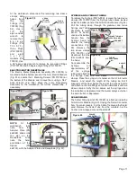
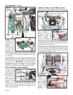
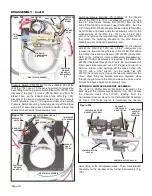
ELECTRIC MOTOR CONTROL PANEL HOUSING
Locate
the
four mounting
screws (PN
510650) on
the bottom of
the Air/Electric
Module Top
Panel
(Fig.
20),
and
remove with a
#2
Phillips
screwdriver.
Disconnect the
Wire Harness
(PN 875113)
from the 4-pin
' J C O M M '
c o n n e c t o r
located on the
Motor Control
Panel Display
Board
(PN
3 3 0 6 0 0 - C )
(see Fig. 21).
Move Motor
Control Panel
to the work-
bench.
D i s c o n n e c t
the Control
P a n e l
M e m b r a n e
flex cable from
the
6-pin
' J K E Y PA D '
connector on
the Display
Board (Fig.
22). If removal
of the Display
Board
is
required, use
needlenose
pliers to pinch
together the
four mounting
studs on the
Control Panel Housing and lift off the Board.
NOTE:
The
Display Board is not a user-serviceable subassembly and
Figure 20
TOP PANEL
MOUNTING SCREWS
(X4)
Figure 18
WATER
FILTER
MOUNTING
BAR
Figure 19
GASKET
CAP
DISASSEMBLY - Cont'd
LUER FITTING
SLEEVE
CLAMP
(X3)
SLEEVE
CLAMP
(X2)
WATER
CAP
MOUNTING
SCREWS
(X3)
FITTINGS
Figure 22
DISPLAY BOARD
FLEX CABLE
CONTROL PANEL MEMBRANE
MOUNTING STUD (X4)
Figure 21
TOP PANEL
ELECTRIC MOTOR
CONTROL PANEL
4-PIN
'JCOMM'
CONNECTOR

