Page 7
should be returned to Aseptico if repairs are required.
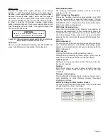
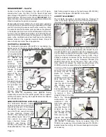
The Control Panel Membrane (PN 420918) is attached to
the front of the Panel Housing with an adhesive backing (see
Fig. 22). Removal of the Membrane is not recommended
unless absolutely necessary. If removal is required, carefully
peel the Membrane out of the recess in the Housing and
permanently discard the entire Membrane. (
IMPORTANT:
Do not reuse an old Membrane - once detached, it should
always be replaced with a brand new Membrane.) To
reinstall a new Membrane: 1) Insert flex cable pigtail through
the slotted hole in the Top Cover; 2) Remove liner from
adhesive backing on new Membrane; 3) Carefully center
new Membrane in recess in Top Cover; and, 4) Press down
evenly on Membrane until firmly adhered to Cover; and 5)
Add 4-inches of 1-inch diameter heat Shrink around Flex
Cable (Do Not Shrink).
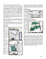
Use a 5/64" Allen wrench to remove the four screws (PN
510037) that attach the two Holder Bar Supports (PN
462096) to the Top Panel (see Fig. 21). Place Supports
aside for reassembly later.
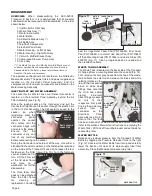
The Rubber Seal strip (PN 520104) is taped to the Top
Panel, along the Panel's back edge (Fig. 23). Peel off the
Seal if necessary, and replace using double-backed
adhesive tape.
REAR WALL
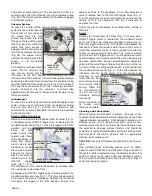
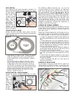
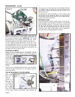
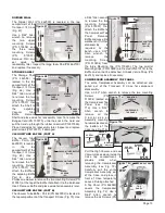
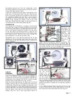
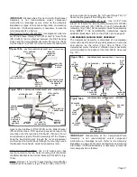
Use a 5/64" Allen wrench to remove the 10 screws (PN
510037)
that
attach the Rear
Wall to the
A i r / E l e c t r i c
Module (Fig. 24).
Note that one
mounting screw
is lo-cated on the
M a n i f o l d
Assembly control
panel and two
more are on the
top panel.
C a r e f u l l y
disconnect the
Rear Wall from
the Module and
swing it to the
right, noting that
the tubing to the
Pressure Toggle
Valve
(PN
730014) is still
a t t a c h e d .
Remove sleeve
Clamp
(PN
730015)
and
detach the clear
tubing (PN AA-
94C) from the
Toggle
Valve.
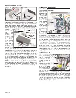
Disconnect Rear
Wall and move to work bench. Remove the two Fittings (PN
730062) and gaskets (PN 730074) with a 1/4" open-ended
wrench. Use a 9/16" wrench to remove the Toggle Valve
mounting nut located on the outside of the Wall, then remove
the Valve.
RIGHT SIDE WALL
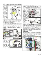
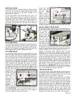
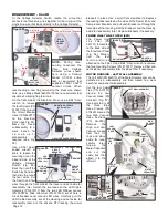
Locate the four mounting screws (PN 510037) that attach
the Right Wall
(PN 462036)
to the Module
(see Fig. 26).
Use a 5/64"
Allen wrench
to remove all
four screws
and set the
Wall aside for re-assembly later.
POWER BOARD AND INSULATORS
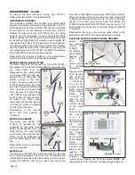
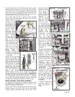
Use a 1/16"
Allen wrench
to remove the
four screws
(PN 510016)
that attach the
clear plastic
Power Board
Insulator (PN
462117) to the
Module (Fig.
27). Remove
Insulator to
expose the
Power Board
(PN 330601), then place Insulator aside for reassembly
later.
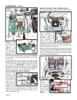
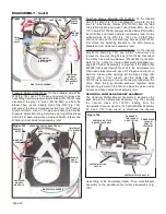
Carefully pull Power Board away from the Module until the
wiring assemblies can be accessed (Fig. 28). Note the
alignment of the Board's mounting holes with the nylon
stand-offs. Unclamp the brass Sleeve (PN 461607) from the
Pressure Sensor Tube (PN 730227). Detach Tube from
'PSENS1' connector on Power Board. Disconnect the Motor
Connector Wiring Assembly (PN 330598) from the
'J_MOTOR' connector on the Board. Note the orientation of
the Wiring Assembly's connector and wires with the locking
tab and position '1' on the Board's connector. Disconnect the
3-pin, 2-pin, and 5-pin (PN's 860118, 860076, and 860019
respectively) connectors from the 'JPWR1', 'J_SLND', and
'J_FOOTPEDAL' connectors on the Board.
MOUNTING
SCREWS
(X10)
Figure 24
REAR WALL
Figure 26
RIGHT WALL
MOUNTING
SCREWS (X4)
Figure 27
MOUNTING
SCREW
(X4)
POWER
BOARD
INSULATOR
TOGGLE
VALVE
FITTING
(X2)
REAR
WALL
TUBE
Figure 25
PRESSURE
RELEASE
TOGGLE
VALVE

