11
Handpiece calibration consists of either a
one-part or two-part procedure, depending
on which type handpiece is used:
Part-1
“Free Run” Calibration - Performed
on both increaser and reduction type
handpieces.
Part-2
“Dyno” Calibration - Performed only
on reduction type handpieces (16:1 to
32:1 ratios). This procedure includes the
“Free Run” Calibration above, plus a
Ratio and Torque Test performed via the
dynamometer.
Calibration - Part 1:
Follow steps
a.
and
b.
below to perform the
Part-1 (“Free Run”) calibration procedure:
a.
Preselect ratio of the handpiece, using
the Ratio Up/Down buttons on the console
keypad.
IMPORTANT:
This step must be
performed prior to calibrating each hand-
piece.
NOTE:
The System supports reduc-
tion handpieces with ratios ranging from
16:1 to 32:1. Prior to calibrating any reduc-
tion handpieces within this range, preselect
the 20:1 ratio setting.
b.
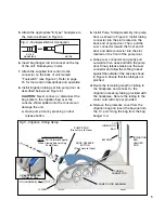
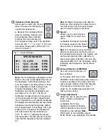
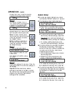
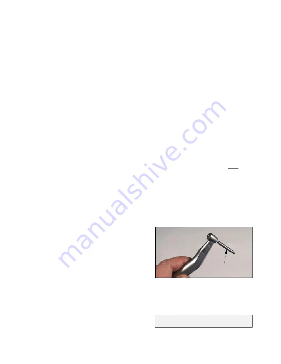
Insert the calibration adapter into the
handpiece as shown in Figure 7. (Adapter
installs in same manner as a bur or tool.)
c.
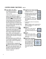
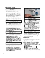
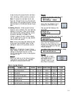
Press and release the Calibration (CAL)
button to activate the Integrated Calibration
Program. The System will run the hand-
piece through the “Free Run” test. Follow
the prompts on the display:
Add Handpiece To Motor
Press 1> Next 3> Exit
user when the handpiece torque level
reaches 75% and 100% of the “MAX” limit.
CAUTION:
Because of the unrestrained
torque characteristics inherent in MAX
Torque Mode operation, it is recommended
that MAX Mode be used only for drilling
procedures in osteotomy or surgical site
preparation. It is also recommended that
the user perform a complete calibration of
the handpiece before operating in MAX
Mode and/or adhere to the torque recom-
mendations of the handpiece manufacturer.
c.
Torque Limit Mode - Depressing the
Torque Modes (“A-S/MAX”) button until nei-
ther the green nor amber LED is lit will
enable Torque Limiting. In this mode, the
handpiece will only operate up to the
torque limit set via the Torque Up/Down
buttons. The handpiece will stop and then
restart once the load is removed. This is
the only Torque Mode available for increas-
er handpieces.
7.
Turn irrigation pump ‘ON’ (green LED illu-
minates) and select the irrigation flow rate
for the handpiece using the “FLOW”
Up/Down buttons.
8.
Select the desired forward or reverse direc-
tion for the handpiece using the
“FWD/REV” button (green/amber LED
will illuminate).
9.
Depress footswitch to activate the motor/
handpiece and irrigation pump. Releasing
the footswitch will stop the motor/handpiece
and pump.
10.Calibration of Handpiece
- Because vari-
ations in handpiece efficiency can cause
inaccuracies in torque, it is essential to rou-
tinely calibrate the handpiece/motor. This
will maintain optimal performance from the
System. It is recommended to calibrate the
System daily, even if using the same hand-
piece, or whenever a handpiece is
changed.
CALIBRATION
ADAPTER
Fig.7 - Adapter Installation


