12
OPERATION
- Cont’d:
Ratio Test In Progress
Please Wait ...
Torque Test In Progress
Please Wait ...
Note:
If the handpiece is not properly con-
nected to the dynamometer, the screen will
display the following message:
Dynamometer Error !
Press: 1> Retry 3> Exit
e.
After a successful calibration of a reduc-
tion handpiece, the screen will display the
following example message:
Ratio = 20.07 Eff = 86%
Press 2> Save 3> Exit
f.
Press ‘2’ to save results. The AEU-7000
will save the exact ratio found by the cali-
bration measurements into the settings for
that reduction handpiece.
Preset Mode:
11.
The six preset memory buttons are prepro-
grammed at the factory with the default
presets shown in Figure 9.
12.
Press the preset number button desired
and the display will indicate the “Label”
(name) and preset number as shown in the
example below:
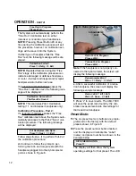
SITE PREPARATION
Preset 1
The display will then show the System
operating settings for that preset. The LED
Free Run In Progress
Please Wait ...
The System will automatically perform the
“Free Run” Calibration test on either
increaser or reduction type handpieces.
NOTE:
Pressing Preset Button #3 at any
time during the calibration process will exit
the procedure, however, no calibration set-
tings will be saved into the System.
If either type of handpiece fails the “Free
Run” test, the following message will be dis-
played:
Calibration Failed !
Press 1> Retry 3> Exit
NOTE:
Repeated failures during this “Free
Run” stage of the calibration procedure can
indicate a damaged or defective handpiece
or motor - Exit test and inspect and/or repair
handpiece/motor before next use.
If a 1:1 or increaser handpiece passes the
“Free Run” calibration test, the following mes-
sage will be displayed:
Calibration Successful !
The Result is Saved
NOTE:
This concludes Part-1 Calibration
testing (1:1 and increaser handpieces only).
Calibration Procedure - Part 2:
If a reduction handpiece passes the “Free
Run” calibration test above, the System auto-
matically advances to the Part-2 “Dyno” cali-
bration procedure. The following message
will be displayed:
Put Handpiece Into Dyno
Press 1> Next 3> Exit
Follow steps
b, d, e, f,
to perform Part-2 of
the calibration procedure:
d.
Continue to follow the prompts, per-
forming the ratio and torque tests with the
handpiece plugged into the dynamometer
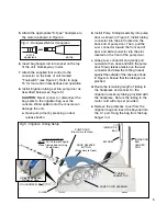
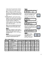
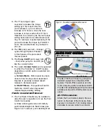
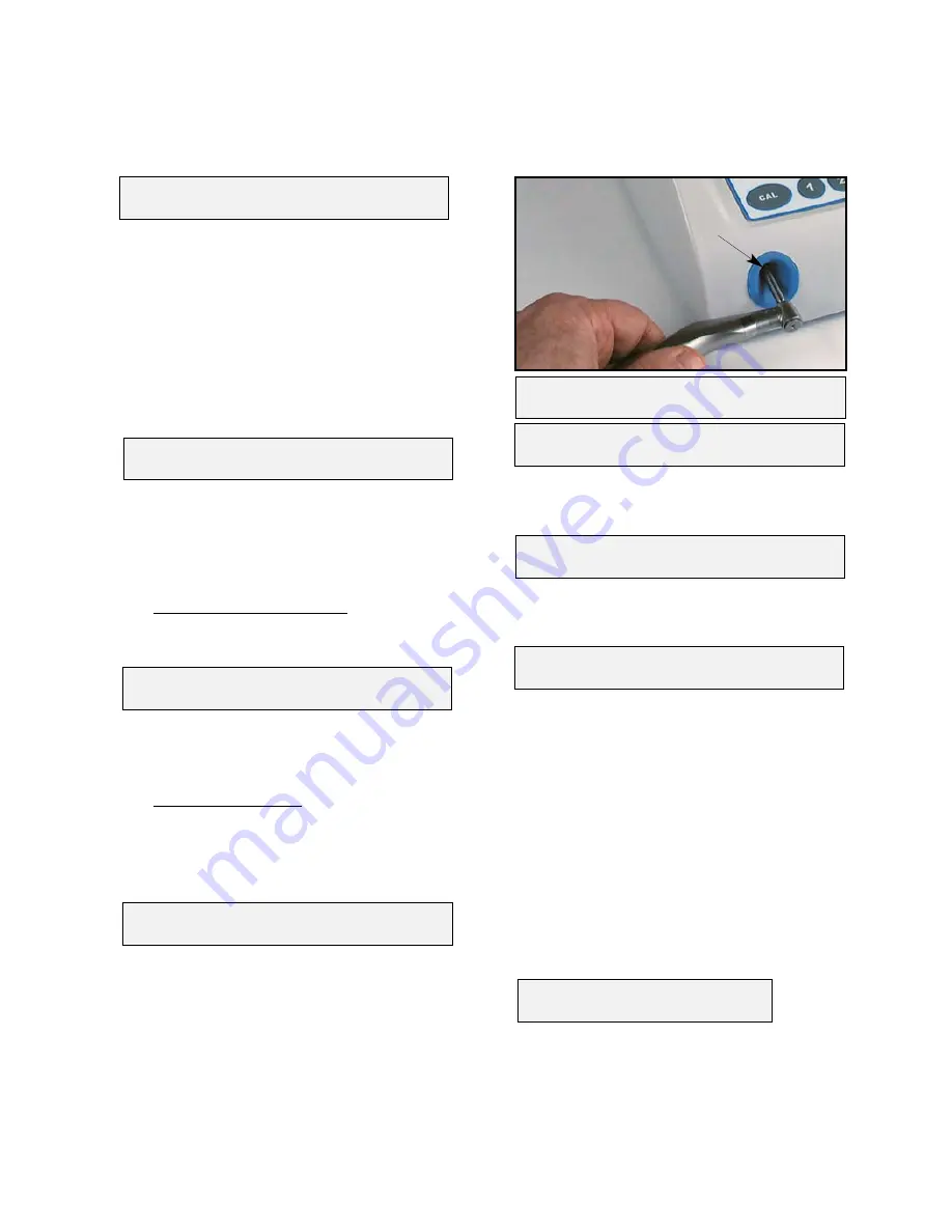
port as shown in Figure 8.
DYNAMOMETER
PORT
Fig.8 - Ratio & Torque Tests


