13
located above the preset button will illumi-
nate, indicating which preset is activated.
Note:
If a preset is activated and its set-
tings are changed in any way, the preset’s
LED will turn off, signifying that the unit has
switched back to the Manual Mode of oper-
ation.
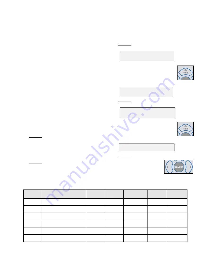
13.Editing Presets
- All six preset memory
buttons can be edited by the user with new
settings, at any time. These new settings
will overwrite the existing settings, includ-
ing factory defaults. In addition, the
“Labels” (names) for each of the presets
can be edited by the user for easy identifi-
cation of the new preset.
Note:
At any time during the following edit-
ing process, the CANCEL button can be
pressed to return to the operation screen.
Step 1:
Adjust each of the Ratio, Speed, Torque,
Flow, Rotation Direction, and Pump On/Off
settings to the desired values via the
control panel buttons (refer to descriptions
on pages 6 - 8).
Step 2:
Press and hold any of the Preset buttons
1 through 6, to save the new, modified
settings into that particular button.
Step 3:
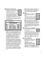
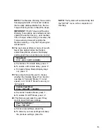
A display prompt then asks the user:
Preset - (X)
Save Settings? YES/NO
Press the ‘Yes’ Button on the
Display to confirm the save.
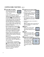
The prompt then displays the
message:
Preset - (X)
Setting Saved
Step 4:
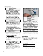
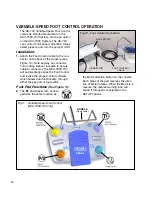
A display prompt then asks the user:
(Label Name)
Edit Label? YES/NO
Press the ‘Yes’ Button on the
Display to confirm that the Label
needs to be edited and the new
Preset renamed.
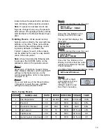
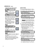
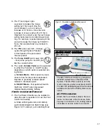
An editing “Help” message displays briefly:
Edit Label With Arrows
Step 5:
Use the Left or Right
arrow buttons to move
the display cursor
left/right under the top
line of text characters.
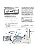
FIG 9 - Factory Presets
PRESET
NAME (Label)
RATIO
SPEED
DIRECTION TORQUE
FLOW
1
Site Preparation
1:2
60,000
FWD
2.75 N•cm
100%
2
Pilot Drill
20:1
1,200
FWD
MAX
80%
3
Finish Drill / Reamer
20:1
800
FWD
MAX
80%
4
Tap Forward
20:1
15
FWD
25 N•cm
30%
5
Tap Reverse
20:1
35
REV
35 N•cm
Off
6
Install Implant / Abutment
20:1
15
FWD
32 N•cm
Off


