5
5.
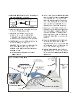
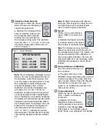
Attach the appropriate "E-Type" handpiece to
the motor as shown in Figure 4.
6.
Insert bag hanger rod into socket on the top
of the unit. Note keyway in slot.
7.
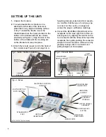
Attach the supplied foot control to the
connector on the back of unit marked
"Footswitch" (see Figure 2). Refer to page
16 for foot control descriptions and operation
8.
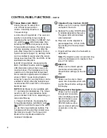
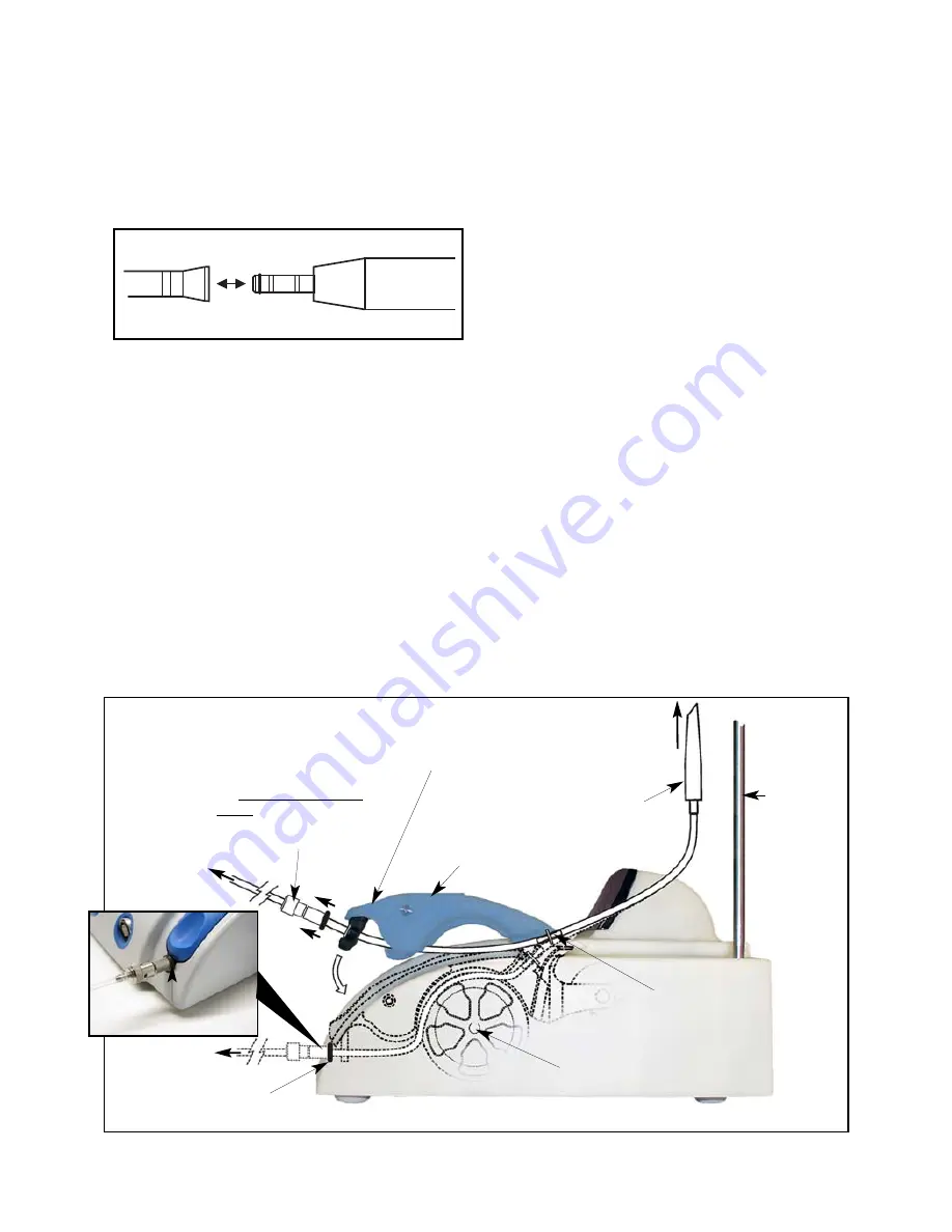
Install irrigation tubing set into pump door as
described below (see Figure 5):
CAUTION:
Never connect or disconnect the
bag spike to the irrigation bag over the
console. Water spilled onto the console can
damage the unit.
a.
Open pump door by pressing on door
release button.
b.
Install Pump Tubing Assembly into pump
door as shown in Figure 5. Install tubing
connector into the slot located on the
back end of pump door. Then, pull the
Luer connector toward the front end of
door and slide connector into the slot
located on the front of the pump door.
c.
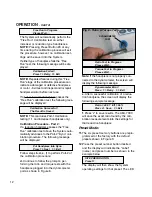
Grasp Luer connector and gently pull
outwards, then close and latch the pump
door. Slowly release tension on the Luer
connector and allow the O-Ring to seat
against the outside of the case as shown
in Figure 5. Ensure that the tubing is not
pinched.
d.
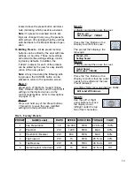
Route the remaining length of tubing to
the handpiece and connect to the
irrigation accessory tubing provided with
the handpiece. Secure the tubing to the
motor cord with clip set provided.
e.
Remove the protective cover from the
irrigation bag and insert the bayonet into
the I.V. port. Hang the bag from the bag
hanger rod.
PUMP DOOR
(Press Here to Close)
TO
IRRIGATION
BAG
PUMP ROTOR ASSEMBLY
BAYONET
IRRIGATION
BAG
HANGER
ROD
DOOR RELEASE
BUTTON
(Press Here to Open)
TUBING
CONNECTOR
Fig.5 - Irrigation Tubing Setup
E-TYPE
HANDPIECE
MOTOR
Fig. 4 - Handpiece/Motor Connection
LUER CONNECTOR
(NOTE: Pull Outwards Slightly
When Closing And Latching
Pump Door.)
O-Ring Seats Against
Outside of Case
(TO HANDPIECE)
(TO HANDPIECE)
O-RING


