background image

Page 9

REASSEMBLY

32.

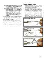
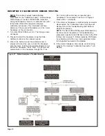
To reassemble the System, perform steps 1-31 above

in the reverse order. 

NOTE:

Follow these recommended Steps to

reassemble the Top Cover to the Chassis:

a.

Prior to attaching Top Cover, loosen the two

Peristaltic Pump Assembly mounting screws.

b.

Loosen only the rear mounting screw on the Motor

Connector bracket, then remove the front mounting

screw. Slide the Motor Connector backwards in the

mounting slot and lightly secure it with the rear

screw.

c.

Carefully work the Top Cover down over the

Chassis and position in place but do not attach to

Chassis bottom. Ensure the flex cable from the

Control Panel is not sharply bent. Partially open the

pump door to allow the Top Cover to work past the

rear of the pump door. Work the Top Cover all the

way down until it’s properly seated against the

Chassis bottom. (Note the four plastic alignment

tabs that engage the four square holes on the

Chassis bottom.)

d.

Use a #2 Phillips screwdriver to install three 3/8”

screws (PN 510406) with three lock washers (PN

510419), and four longer 2½” screws (PN 510643)

and lock washers (PN: 510419), through the

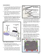
Chassis bottom into the Top Cover, as shown on

Figure 8, page 3. 

f.

Reposition the Peristaltic Pump frontwards or

backwards until it just clears the Cover at the front

when opened. Tighten the two Pump mounting

screws.

g.

Slide the Motor Connector forward until it protrudes

out through the blue bezel in the front of the Unit.

Reinstall the front 3/8” mounting screw (PN

510406) with lock washer (PN 510419) and tighten

both mounting screws.

h.

Open and close the Pump door several times and

verify that the door opens, closes, and latches

smoothly. Readjust Pump position if necessary.

i.

Connect Foot Pedal and Motor. Insert a length of

Pump tubing into the peristaltic pump (refer to

Operator’s Manual for instructions on setting up

Pump/tubing). Verify that the Pump latches

securely.

j.

Power AEU-7000L/7000E Unit ‘On’.

k.

With the “Flow” ‘On/Off’ button set to ‘On’ and the

Pump flow rate set to 100%, depress the Foot

Control and verify the Pump runs.

Summary of Contents for AEU-7000E-70V

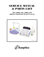
Page 1: ...SERVICE MANUAL PARTS LIST AEU 7000L 70V 7000E 70V Implant Endodontic Dental Systems AEU 7000L 70V System ...

Page 2: ...25 AEU 7000E Parts List 26 27 Symbol Definitions 28 Tools List 28 Warranty 29 Notes 29 P O Box 1548 Woodinville WA 98072 1548 1 800 426 5913 425 487 3157 Fax 425 487 2608 email info aseptico com Internet www aseptico com Persons performing repairs to active electronic circuitry or operating High Voltage e g HiPot test equipment must have training or experience performing similar servicing activiti...

Page 3: ...ion tubing refer to System Troubleshooting on page 20 Turn the power switch on the rear panel of the console to the On position The vacuum fluorescent display should show the startup screen for a few seconds then default to the operating parameters of the last used preset or preset 1 if the factory setup was recalled The startup screen will display the Aseptico logo and then the software version o...

Page 4: ... and Standards Employees handling electronic sub assemblies and ESD sensitive components are expected to be trained Training should be based on IPC A 610 or equivalent ESD standard ANSI ESD S 20 20 Protection of Electrical and Electronic Parts Assemblies and Equipment ESD Static Controlled Area Areas that are designated for handling and working on electronic sub assemblies or their components shou...

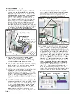
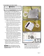
Page 5: ...te two screws PN 510406 and lock washers PN 510419 that attach Motor Connector Bracket to Chassis see Fig 8 Remove only the front screw and washer with a 2 Phillips screwdriver Loosen but do not remove second screw and washer located in slotted hole 7 Slide Motor Connector PN 875073 and Bracket backwards in slotted hole so that Connector disengages from blue bezel in cover Lightly tighten mounting...

Page 6: ...y off the two studs PN 510625 and place Assembly aside for reuse later NOTE The Display Assembly is a non service able component of the AEU 7000 System If not functioning properly either replace Display with a new Assembly or return Display to Aseptico for repairs When installing a new Assembly ensure that Display header is properly oriented to Cover cutout The header should be positioned on right...

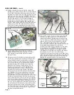
Page 7: ...hole in Cover Set Bezels aside for reuse later NOTE When remounting Bezels ensure that locking tabs fully snap over edges of holes into grooves provided on inside of Cover 18 Cut and remove the cable tie surrounding the cable bundle on right hand side of PCB Assembly see Fig 15 Detach Pump Assembly cable connector at J1 Pump location on PCB Assembly Make note of pin wire alignments of connectors b...

Page 8: ...reassembling Motor Connector subassembly insert Motor Connector from inboard side of Bracket outwards through Bracket cutout Align the flats on Connector barrel with flats on cutout and ensure white alignment mark on Connector is position ed at the top Apply a drop of white glue PN 490142 to the Connector threads before installing round and hex nuts From outboard side of Bracket thread round nut u...

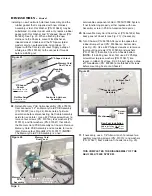
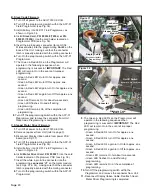
Page 9: ...attached to the outside terminal on Power Inlet Assembly 25 Use a small screwdriver to detach and remove Fuse Drawer PN 840060 from Power Inlet Assembly see Fig 21a Remove two Fuses PN 830040 from Fuse Drawer if necessary Press in the five locking tabs on inboard side of Power Inlet Assembly PN 840086 and push Assembly outward through cutout in back panel of Chassis see Fig 21b Set Assembly aside ...

Page 10: ...m If not functioning properly either replace with new Assembly or return PCB to Aseptico for repairs 29 Remove Memory Card Dust Cover PN 461606 from back panel of Chassis see Fig 23 if necessary 30 Turn Chassis PN 461955 08 over to expose four rubber Bumper Feet PN 850066 on bottom side see Fig 25 Use a 2 Phillips screwdriver to remove four mounting screws PN 510406 and washers PN 510431 that atta...

Page 11: ...s bottom d Use a 2 Phillips screwdriver to install three 3 8 screws PN 510406 with three lock washers PN 510419 and four longer 2 screws PN 510643 and lock washers PN 510419 through the Chassis bottom into the Top Cover as shown on Figure 8 page 3 f Reposition the Peristaltic Pump frontwards or backwards until it just clears the Cover at the front when opened Tighten the two Pump mounting screws g...

Page 12: ...process verifying that the calibration completed successfully If calibration fails refer to page 12 for Calibration Error Testing instructions Press the SELECT button again to return to Implant Mode 8 Connect an AE 70V2 foot control and depress each of the buttons Verify that the function of each switch is from lower left clockwise Preset Increment Motor direction Torque Increment Flow ON OFF Sele...

Page 13: ...6C Rotor Rotation Test Rotate Test Tool 12 8 Press the blue standby button and verify that the display goes blank Press the standby button again to reactivate the display 12 9 Press and hold Preset 1 Answer YES to save the settings Answer YES to edit the label Use the left and right arrow keys and verify that the cursor moves Use the up YES and down NO keys and verify that the letters change Press...

Page 14: ...er bur or bit into the handpiece Press Next The System will automatically run the handpiece through the Free Run test on either increaser or reduction type handpieces The message Free Run In Progress Please Wait will display 4 If the motor or handpiece is malfunctioning jammed or disconnected the Calibration Failed message will display Consult the troubleshooting chart below to pinpoint the proble...

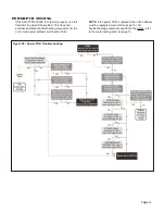
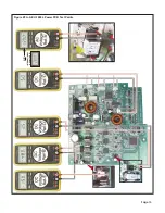
Page 15: ...hart provides additional troubleshooting procedures for the unit s main power printed circuit board PCB NOTE If the power PCB is replaced the unit s software must be reprogrammed refer to page 19 For troubleshooting procedures specific to the motor refer to the motor testing chart on page 12 Figure 28 Power PCB Troubleshooting ...

Page 16: ...y output is not present replace Power Supply If 48VDC output is present from Supply replace PCB board Turn AEU 7000L 7000E power switch Off after 48VDC test is completed Dangerous voltages are present during the following board testing Severe electric shock can result and could prove fatal Only qualified technicians should perform these tests WARNING 4 5V DC Check This test verifies that proper DC...

Page 17: ...Page 15 Figure 29A AEU 7000L Power PCB Test Points INTERNATIONAL AC VOLTAGE OR ...

Page 18: ...Page 16 Figure 29B AEU 7000E Power PCB Test Points AEU 7000E POWER PCB ASSEMBLY AC INLET WIRING ASSEMBLY INTERNATIONAL AC VOLTAGE OR ...

Page 19: ...st between Mains at the power inlet and the pump drain opening see Fig 30 Perform test with the power inlet switch in the ON position Test parameters are 2520 VDC for one second with an allowed leakage current of 1 0mA 1 4 Conduct a Dielectric Withstand Test between Mains at the power inlet and the motor housing see Fig 31 Test is to be performed with the power inlet switch in the ON position and ...

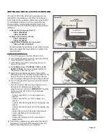
Page 20: ...until a click is felt then release the card 4 Turn the Main Power Switch on the back panel On 5 The Display will show the following message Press the Yes key on the Control Panel 6 The Display will then show the following message Press the Yes key on the Control Panel 7 The Display will show the following message A status bar will indicate the progress of the programming 8 When the programming is ...

Page 21: ...CB see Fig 35 5 Insert the 4 pin square connector for an HC08 Microcontroller into the programming Port 1 on the back of the Unit making sure that the connector latch is properly oriented with the mating connector 6 Turn On the programming switch within the AFP 01 Programmer 7 The Green Red LED s on the Programmer will operate in the following sequence when programming is successful IMPORTANT The ...

Page 22: ...r 6 Turn On the programming switch within the AFP 01 Programmer 7 The Green Red LED s on the Programmer will operate in the following sequence when programming is successful IMPORTANT The Red LED will remain On in the event of improper programming Green Red LED s turn On for approx one second Green Red LED s turn Off for approx one second Green Red LED s again turn On for approx one second Green R...

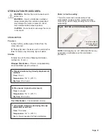
Page 23: ...n appropriately sized sterilization pouch and seal it A Standard autoclaving Gravity displacement method Time 15 min Temperature 132 C 270 F Dry time 30 minutes B Pre vacuum dynamic air removal Time 4 minutes Temperature 132 C 270 F Dry time 40 minutes Flash Sterilization For immediate use only C Unwrapped standard autoclaving Gravity displacement method Time 10 minutes Temperature 132 C 270 F No ...

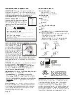
Page 24: ...ving stand handpiece by its base on a paper towel and allow excess oil to drain see Figure 40 AEU 7000L MOTOR LED LENS CLEANING The lens of the LED light on the AEU 7000L motor see Fig 41 is soft and can be damaged It should not be exposed to dust and debris Excessive dust and debris may cause a drastic decrease in optical output In the event that the light requires cleaning first try a gentle swa...

Page 25: ...ew section from the extra tube set provided with the system Check for dirty under lubricated handpiece Check if handpiece lubricant is draining into motor After lubricating and before autoclaving stand handpiece on its base to let excess lubricant drain out Verify that ratio setting matches handpiece ratio Use calibration function Turn power switch Off wait 5 seconds then turn back On to reset Gra...

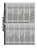
Page 26: ...DESCRIPTION PART NO Qty 34 35 36 37 CLAMP CABLE NYLON 5 16 DIA X 203 HOLE 510410 1 35 BRACKET DYNAMOMETER AEU 7000 461551 1 36 NUT NYLON LOCK 6 32 510745 3 38 GROMMET 1 4 NEOPREME BLK 870185 3 39 SPACER NYL 1 4RND X 1 4LX 6 510163 3 40 ADAPTER DYNAMOMETER 461540 1 41 SETSCREW 8 32X1 8 S S CUP POIN 510278 1 42 DYNAMOMETER ASSEMBY 330481 1 43 M S PHD PHL M3X 5X6 SEMS W WSR 510627 4 INSULATOR DYNAMOM...

Page 27: ... 32 33 4 5 7 7 8 31 9 10 11 10 12 10 14 10 9 19 18 19 20 21 22 21 22 25 10 9 26 10 9 30 9 29 30 9 10 9 33 34 36 35 47 46 44 45 41 42 43 40 47 46 49 50 58 59 61 62 62 54 63 63 65 31 55 63 62 54 66 9 37 67 69 Figure 43 AEU 7000L PARTS 27 31 37 48 51 30 53 52 31 55 30 53 57 60 31 30 9 52 35 56 2 3 ...

Page 28: ...EM DESCRIPTION PART NO Qty 34 35 36 37 CLAMP CABLE NYLON 5 16 DIA X 203 HOLE 510410 1 35 BRACKET DYNAMOMETER AEU 7000 461551 1 36 NUT NYLON LOCK 6 32 510745 3 38 GROMMET 1 4 NEOPREME BLK 870185 3 39 SPACER NYL 1 4RND X 1 4LX 6 510163 3 40 ADAPTER DYNAMOMETER 461540 1 41 SETSCREW 8 32X1 8 S S CUP POIN 510278 1 42 DYNAMOMETER ASSEMBY 330481 1 43 M S PHD PHL M3X 5X6 SEMS W WSR 510627 4 INSULATOR DYNA...

Page 29: ... 32 33 4 5 7 7 8 31 9 10 11 10 12 10 14 10 9 19 18 19 20 21 22 21 22 25 10 9 26 10 9 30 9 29 30 9 10 9 33 34 36 35 47 46 44 45 41 42 43 40 47 46 49 50 58 59 61 62 62 54 63 63 65 31 55 63 62 54 66 9 37 67 69 Figure 44 AEU 7000E PARTS 27 31 37 48 51 30 53 52 31 55 30 53 57 60 31 30 9 52 35 56 2 3 ...

Page 30: ...ue Step Through Pump On Off Temperature Limitation Atmospheric Pressure Limitation Humidity Limitation Sterilize At 132 C 270 F Part Number Serial Number 12 Motor Rotation Tool Consult Aseptico for availability PN AE 43 13 Standard Voltmeter Multimeter For testing Power PCB 14 Hi Pot Tester For Dielectric Withstand Test 15 Firmware Programming Tool PN AFP 01 with latest Software AEU 7000L PNs 8900...

Page 31: ...vice will provide instructions usually directing that the product be returned for service Shipment to Aseptico and the cost thereof is always the responsibility of the purchaser Accidental misuse inappropriate installation or failure to perform directed maintenance voids the warranty Deliberately defacing modifying or removing the serial number voids the warranty Aseptico does not assume under thi...

Page 32: ...SE Woodinville WA 98072 1548 1 800 426 5913 425 487 3157 Fax 425 487 2608 Internet www aseptico com Email info aseptico com For Further Service And Or Technical Assistance Contact PRINTED IN THE USA P N 420915 Rev G ECO 14673 03 2019 ...

Reviews: