Page 14
IMPORTANT
The Power PCB is a non-serviceable component of
the AEU-7000L/7000E Systems. If not functioning
properly the PCB should either be replaced with a
new Assembly or returned to Aseptico for repairs.
POWER PCB TESTING POINTS
1.
Turn AEU-7000L/7000E power switch ‘Off’. Remove
irrigation bag, tubing, and rod. Disconnect motor/cable
and foot control. Disassemble top cover from chassis
(refer to page 3). Place unit upright on work bench to
expose internal Power PCB.
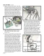
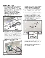
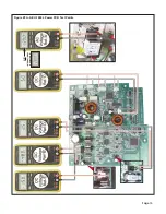
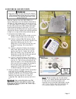
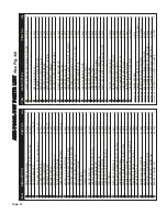
2. 120V (US) or 230V (International) AC Check:
This
test verifies that the fuses are good and the proper AC
voltage is being provided to the power PCB circuit.
Connect voltmeter test leads to contacts as indicated in
AC Voltage Ref. ‘A’, Figs. 29A&B. Turn AEU-
7000L/7000E power switch ‘On’ .
CAUTION: High voltages present - only qualified
technicians should perform this test. Use extreme
caution to avoid severe electric shock.
If 120V(+/-10V) (US) or 230V(+/-15V) (Internatonal) AC
is not present, check power switch and fuses first, then
if proper voltage still not present, replace Power
Inlet/Fuse Holder assembly.
Turn AEU-7000L/7000E power switch ‘Off’ after 120V
or 230V AC test is completed.
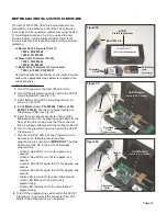
3. 48V DC Check:
This test verifies that proper DC voltage
is being provided to the power PCB circuit. Connect
voltmeter test leads to contacts as indicated in DC
Voltage Reference ‘B’, Figs. 29A&B. Turn AEU-
7000L/7000E power switch ‘On’.
CAUTION: High voltages present - only qualified
technicians should perform this test. Use extreme
caution to avoid severe electric shock.
If 48V(+/-1.0V) DC is not present:
a.
Disconnect 48VDC Cable from Power PCB
connector ‘J2’.
b.
Check 48VDC Cable output from DC Power Supply
for 48VDC(+/-1.0V).
c.
If 48VDC(+/-1.0V) Supply output is not present,
replace Power Supply. If 48VDC output is present
from Supply, replace PCB board.
Turn AEU-7000L/7000E power switch ‘Off’ after 48VDC
test is completed.
Dangerous voltages are present during the following
board testing. Severe electric shock can result and
could prove fatal. Only qualified technicians should
perform these tests.
WARNING
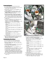
4. 5V DC Check:
This test verifies that proper DC
voltage is being provided to the key pad, foot pedal,
flash card, programming ports, and other PCB
components. Connect voltmeter test leads to contacts
as indicated in DC Voltage Reference ‘C’, Figs.
29A&B. Turn AEU-7000 power switch ‘On’.
CAUTION: High voltages present - only qualified
technicians should perform this test. Use extreme
caution to avoid severe electric shock.
Replace PCB board if 5V(+/-0.2V) DC is not present.
Turn AEU-7000L/7000E power switch ‘Off’ after 5VDC
test is completed.
5. 2.5V DC Check:
This test verifies that proper DC
voltage is being provided to the motor and other PCB
components. Connect voltmeter test leads to contacts
as indicated in DC Voltage Reference ‘D’, Figs.
29A&B. Turn AEU-7000L/7000E power switch ‘On’.
CAUTION: High voltages present - only qualified
technicians should perform this test. Use extreme
caution to avoid severe electric shock.
Replace PCB board if 2.5V(+/-0.2V) DC is not present.
Turn AEU-7000L/7000E power switch ‘Off’ after
2.5VDC test is completed.
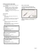
6. 15V DC Check:
This test verifies that proper DC
voltage is being provided to the motor and other PCB
components. Connect voltmeter test leads to contacts
as indicated in DC Voltage Reference ‘E’, Figs.
29A&B. Turn AEU-7000L/7000E power switch ‘On’.
CAUTION: High voltages present - only qualified
technicians should perform this test. Use extreme
caution to avoid severe electric shock.
Replace PCB board if 15V(+/-1.0V) DC is not present.
Turn AEU-7000L/7000E power switch ‘Off’ after 15VDC
test is completed.

