Page 20
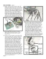
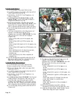
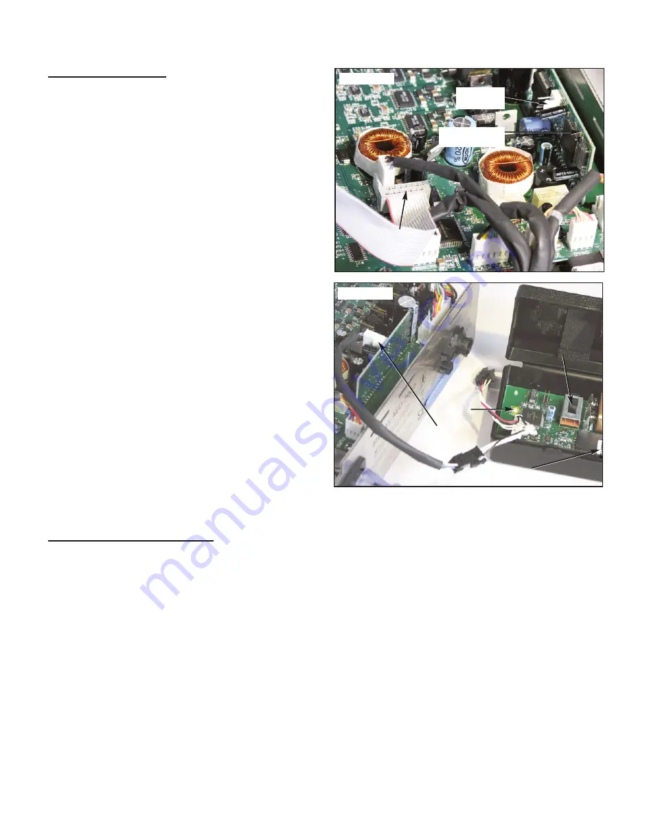
Figure 37
Display Cable
(Disconnect before
Programming)
‘J1’
Connector
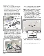
Figure 38
9.
The Green & Red LED’s on the Programmer will
operate in the following sequence when
programming is successful:
IMPORTANT:
The Red
LED will remain On in the event of improper
programming.
• Green & Red LED’s turn On for approx. one
second.
• Green & Red LED’s turn Off for approx. one
second.
• Green & Red LED’s again turn On for approx. one
second.
• Green & Red LED’s again turn Off for approx. one
second.
• Green LED remains On for about two seconds.
• Green LED flashes On and off during
programming.
• Green LED remains On at the completion of
programming.
10.
Turn Off the programming switch within the
Programmer and remove the connector from Unit.
11.
Reconnect Display ribbon Cable. Reattach Cover.
Motor Driver Programming is completed.
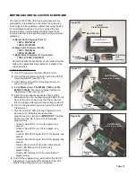
B. Slave Code Firmware
1.
Turn Off all power to the AEU-7000L/E Units.
2.
Turn Off the programming switch within the AFP-01
Field Programmer (see Fig. 36).
3.
Install battery into AFP-01 Field Programmer, as
shown in Figure 36.
4.
Install
Slave Card, PN: 890049 (7000L) or PN:
890023 (7000E)
, into the card holder located on
Programmer PCB (see Fig. 36).
5.
Insert the 4-pin square connector (for an HC08
Microcontroller) into the programming
Port-2
on the
back of the Unit, making sure that the connector
latch is properly oriented with the mating connector.
6.
Turn On the programming switch within the AFP-01
Programmer.
7.
The Green & Red LED’s on the Programmer will
operate in the following sequence when
programming is successful:
IMPORTANT:
The Red
LED will remain On in the event of improper
programming.
• Green & Red LED’s turn On for approx. one
second.
• Green & Red LED’s turn Off for approx. one
second.
• Green & Red LED’s again turn On for approx. one
second.
• Green & Red LED’s again turn Off for approx. one
second.
• Green LED remains On for about two seconds.
• Green LED flashes On and off during
programming.
• Green LED remains On at the completion of
programming.
8.
Turn Off the programming switch within the AFP-01
Programmer and remove the connector from Unit.
Slave Code Programming is completed.
C. Stepper Motor Driver Firmware
1.
Turn Off all power to the AEU-7000L/E Units.
2.
Remove top cover from Unit (refer to page 3).
3.
Disconnect Display ribbon cable from power PCB
board (see Fig. 37).
4.
Turn Off the programming switch within the AFP-01
Field Programmer (see Fig. 38).
5.
Install battery into AFP-01 Field Programmer, as
shown in Figure 38.
6.
Install
Motor Driver Card, PN: 890021
, into the card
holder located on Programmer PCB (see Fig. 38).
7.
Insert the white 4-pin in-line connector into the
programming
connector ‘J1’
on the motor module
(see Figs. 37 & 38), making sure that the connector
latch is properly oriented with the mating connector.
8.
Turn On the programming switch within the AFP-01
Programmer.
‘J1’
Connector
Green
LED
On/Off Switch
(Shown in ‘On’ Position)
Firmware Card
(Motor Driver)
Stepper Motor
Module

