Page 3
DISASSEMBLY
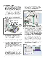
1.
Turn the main power switch OFF. Unplug Power Cord,
PNs: 840079 (US) or 840078 (EURO), from AC Inlet
Connector. (NOTE: Grasp connector plug at end of
Power Cord when removing cord from Unit – do not
pull on cable.)
2.
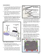
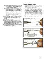
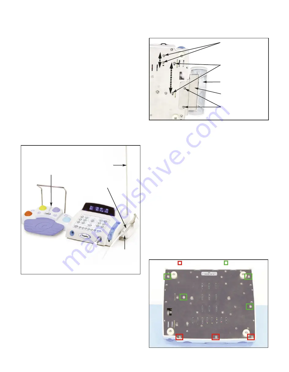
Remove irrigation bag and irrigation tubing sets (PNs:
AE-23) from Unit. Remove Bag Holder Rod (PN:
461541) from Unit by pulling straight up and out of
socket (see Fig. 7). Note alignment of rod pin with
keyway in socket.
3.
Disconnect Motor/Cord Assembly (PN: AE-230L-40 or
AE-230M-40) and Foot Control Assembly (PN: AE-
70V2) from Unit (see Fig. 7).
NOTE:
The Motor/Cord
Assemblies and Foot Control Assembly can be
returned to Aseptico if repair services are necessary --
consult Aseptico Repair Department for more
information.
TOP COVER DISASSEMBLY:
4.
Remove Motor Cradle (PN: 461561) and
Dynanometer Adapter (PN: 461558) (see Fig. 7). Turn
Unit over and gently lay face down onto padded
surface to prevent scuffing.
5.
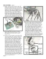
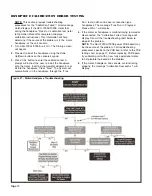
Using a #2 Phillips screwdriver, remove two screws
(PN: 510406) and lock washers (PN: 510419) that
attach Motor Cradle Bracket to Chassis (see Fig. 8).
Remove Bracket and set aside for reassembly later.
6.
Locate two screws (PN: 510406) and lock washers
(PN: 510419) that attach Motor Connector Bracket to
Chassis (see Fig. 8). Remove only the front screw
and washer with a #2 Phillips screwdriver. Loosen, but
do not remove, second screw and washer located in
slotted hole.
7.
Slide Motor Connector (PN: 875073) and Bracket
backwards in slotted hole so that Connector
disengages from blue bezel in cover. Lightly tighten
mounting screw to secure Connector/Bracket in place.
8.
Locate two screws (PN: 510406) and lock washers
(PN: 510419) that mount Peristaltic Pump Assembly
(PN: 330471) to Chassis (see Fig. 8). Using a #2
Phillips screwdriver, loosen but do not remove, both
screws and lock washers. Slide Pump Assembly
forward in slotted mounting holes provided.
9.
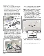
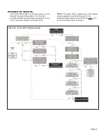
Using a #2 Phillips screwdriver, remove three short
screws (PN: 510406) and lock washers (PN: 510419)
located along forward edge of Unit (see Fig. 9).
Remove four longer screws (PN: 510643) and lock
washers (PN: 510419) that attach Top Cover
subassembly to Chassis.
Figure 8
Motor Cradle
Motor Cradle Bracket
Motor Cradle Bracket
Mounting Screws &
Lockwashers (2)
Motor Connector
Bracket Mounting
Screws & Washers (2)
Peristaltic Pump
Mounting Screws &
Lockwashers (2)
= Short Mtg. Screws
= Long Mtg. Screws
Figure 9
Figure 7
Motor & Cord
Assembly
Motor Cradle
with
Dynamometer
Adapter
Foot Control
Assembly
Bag Holder
Rod

