Page 4
10.
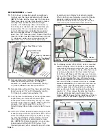
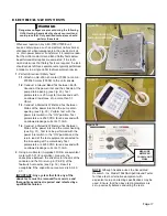
Turn Unit over and position upright on workbench.
Carefully work Top Cover subassembly off Chassis.
(
NOTE:
To help clear the Cover past the Pump door,
follow these steps: a) Slide Pump forward in slotted
mounting holes; b) Carefully lift Cover straight
upwards, until it disengages from Chassis base; c)
Push Pump door release button and hold Door ajar
approximately 1/4 inch - do not allow door to fully
open; d) With door ajar, manipulate Cover up and
over the rear edge of door; e) Allow Door to fully
open; then, f) Lift Cover up and off Chassis.) Rest Top
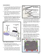
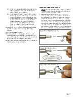
Cover on its side, next to Chassis as shown in Figure
10, taking care not to kink or sharply twist the flex
cables from Cover’s Control Panel and Display.
11.
Note orientation of red stripe on Display Ribbon
Cable (PN: 870300) with Pin #1 on "Display"
connector ‘J7’, located on PCB Assembly (see Fig.
10). Detach Ribbon Cable from connector ‘J7’.
12.
Note orientation of Control Panel flex cable with “Key
Board” connector ‘J14’ on PCB Assembly (see Fig.
10). Detach flex cable from connector ‘J14’.
13.
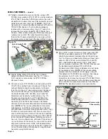
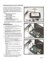
Turn Top Cover subassembly over and lay face down
on protective pad. Remove four spacers (PN:
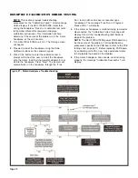
461560) from Cover if necessary (see Fig. 10). Note
orientation of red stripe on Display Ribbon Cable with
connector ‘CN3’ on Display PCB (see Fig. 11).
Detach Display Ribbon Cable and set aside for reuse
later.
14.
Use a 3/16" wrench to remove two mounting nuts (PN:
510005) and split washers (PN: 510004) from Vacuum
Fluorescent Display Assembly (PN: 330503) (see Fig.
11). Carefully lift Display Assembly off the two studs
(PN: 510625) and place Assembly aside for reuse
later. (
NOTE:
The Display Assembly is a non service-
able component of the AEU-7000 System. If not
functioning properly, either replace Display with a new
Assembly or return Display to Aseptico for repairs.
When installing a new Assembly, ensure that Display
header is properly oriented to Cover cutout. The
header should be positioned on right side of cutout
when viewing the inverted Cover from the front.)
15.
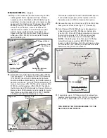
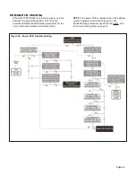
The Display Gasket (PN: 461549), which is mounted
under the Display Filter (PN: 461548), uses double-
sided adhesive backing to adhere the Filter to the Top
Cover (see Fig 12). Remove Display Filter from Cover
by pushing outwards on Filter from inside the Cover.
Push firmly with fingers until Filter pops out (take care
not to scratch Filter). Place Filter aside for reassembly
later. Peel old Gasket from face of Display housing
and discard. (
NOTE:
A new Gasket must be installed
each time the Filter is removed from Cover -
do not
reuse an old Gasket
.) To reassemble Filter and new
Gasket, remove liner from back side of Gasket and
carefully apply Gasket to housing face, aligning its
outer periphery to the raised edge on housing face
(see Fig. 12). Then, remove the other liner from the
front side of Gasket and press Display Filter onto
Gasket. (
NOTE:
Ensure that the inside face of Filter is
clean and free of dust before applying to adhesive.)
DISASSEMBLY -
Cont’d
Display Ribbon Cable
Figure 10
(Red Stripe)
J7 “Display” Connector
Control Panel Ribbon Cable
J14 “Key Board”
Connector
Display Ribbon
Cable Connector CN3
(Header)
Display Ribbon Cable
Figure 11
Mounting Stud
w/Hardware (X2)
Display
Assembly
Figure 12
Display Filter
Display
Display Gasket
Spacer (X4)

