Page 7
Ground Cable
Power Inlet
Assembly
(Black Wire To Outside
Terminal)
component of the AEU-7000L/7000E System. If not
functioning properly, either replace with a new
Assembly or return it to Aseptico for repair.)
23.
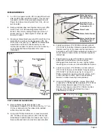
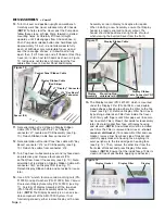
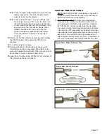
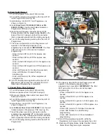
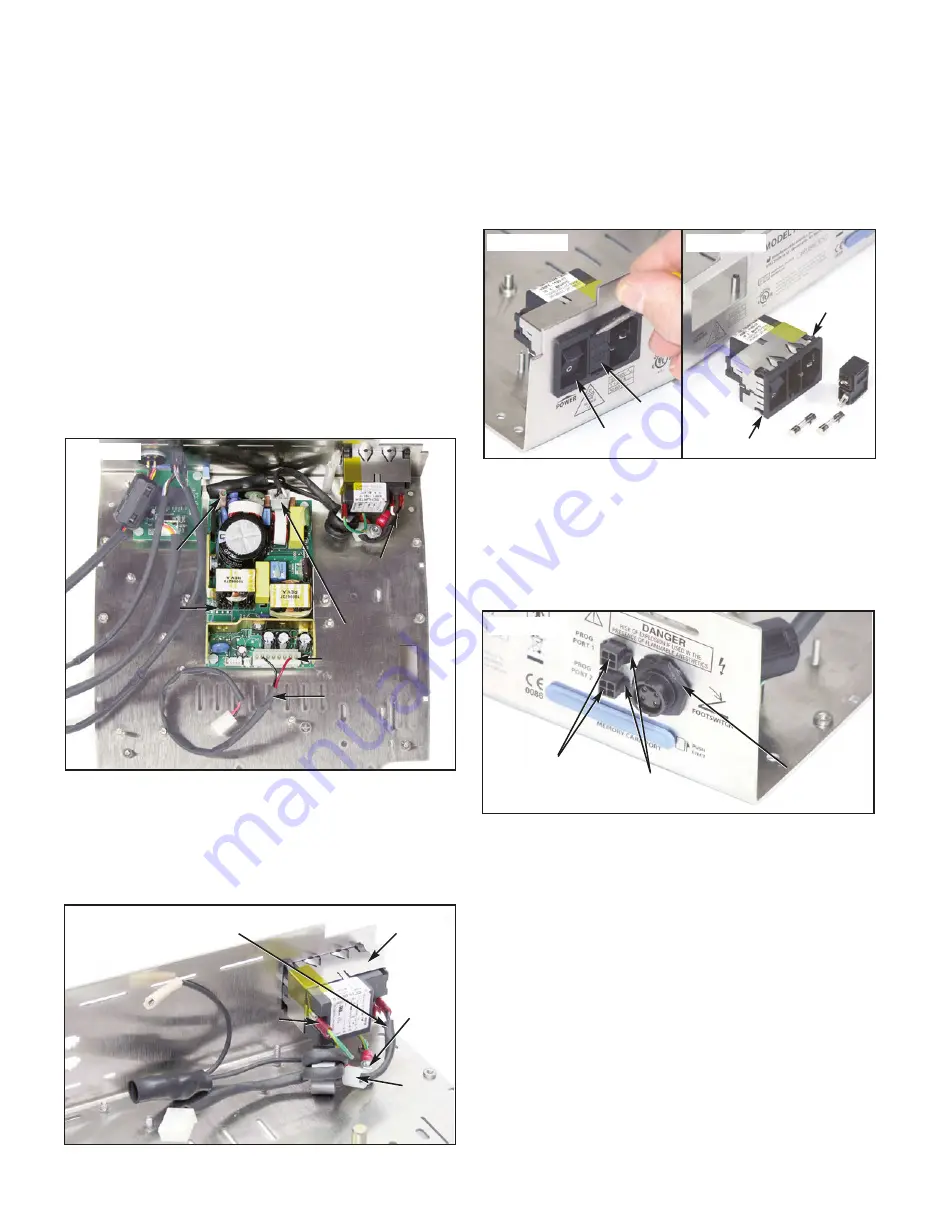
On the 48VDC Power Supply Assembly (PN: 840113),
detach AC Line-In Cable Assembly (PN: 875077) from
connector 'J1’, and 48V DC Cable Assembly (PN:
875076) from connector 'J2' (see Fig. 19). Make note
of pin/wire orientation before disconnecting Cables.
Use a #2 Phillips screwdriver to remove four screws
(PN: 510746), lock washers (PN: 510010), and flat
washers (PN: 510587) that attach Power Supply to
Chassis. Remove Power Supply and set aside for
reuse later. Remove Standoffs (PN: 510747). (
NOTE:
The Power Supply Assembly is a non-serviceable
component of AEU-7000L/7000E System. If not
functioning properly, replace with new Assembly.)
24.
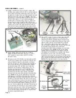
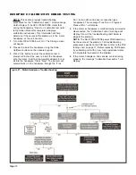
Locate ground stud adjacent to Power Inlet Assembly
(see Fig. 20). Use a 5/16" wrench to remove two kep
nuts (PN: 510006) and external star washers (PN:
510007) that attach Cable Clamp (part of the AC Line
In Cable) and Ground Cable Assemblies (PNs:
875075 and 875112) to stud. Detach AC Line-In Cable
(PN: 875077) and Ground Cable wire connectors from
spade terminals on Power Inlet Assembly (PN:
840086). Make note of wire/terminal orientation before
removing Cables. (
NOTE:
During reassembly, ensure
that the black wire of AC Line-In Cable is attached to
the outside terminal on Power Inlet Assembly.)
25.
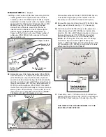
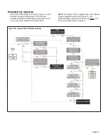
Use a small screwdriver to detach and remove Fuse
Drawer (PN: 840060) from Power Inlet Assembly (see
Fig. 21a). Remove two Fuses (PN: 830040) from Fuse
Drawer if necessary. Press in the five locking tabs on
inboard side of Power Inlet Assembly (PN: 840086)
and push Assembly outward through cutout in back
panel of Chassis (see Fig. 21b). Set Assembly aside
for reuse later.
26.
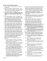
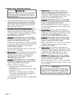
On outboard side of Chassis back panel, use pliers to
pinch together the two locking tabs on the sides of the
two Programming Cables (PN: 875057-01) (see Fig.
22). Push cable connectors inward through port
cutouts in Chassis, noting alignment of keyway on
bottom of connectors. Remove Cables and set aside
for reuse later.
27.
Use a 13/16" wrench to remove mounting nut on
outboard side of Footswitch Harness Assembly, PN:
875074 (see Fig. 22). (
NOTE:
Take care to protect the
back panel against scratches when removing nut.)
Remove plastic 'D' shaped spacer, PN: 461692
(
NOTE:
‘D’ shaped spacer is used on older model
units only). Push Harness Assembly inward through
'D' shaped cutout in Chassis. Note top center position
of keyway on threaded connector. Remove Harness
Assembly and set aside for reuse later. (
NOTE:
If
Figure 19
Connector ‘J2’
Power
Supply
Assembly
48V DC Cable
Connector ‘J1’
AC Line-In
Cable’
Figure 20
AC Line-In Cable
Ground
Stud
Cable
Clamp
(Part of AC
Line-In Cable)
Power Inlet
Assembly
Fuse
Drawer
Locking Tab (X5)
Figure 21a
Figure 21b
Locking
Tabs
Figure 22
Port 1 & Port 2
Programming
Cables
Footswitch
Harness
Mounting Nut
Ground
Cable

