background image

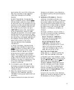
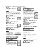
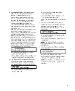
files, press and then quickly release the

pad repeatedly.

Note:

The following message will appear

briefly whenever any 

Endo

Preset is

accessed for the first time, or after factory

defaults have been restored:

Loading Default Series

Please Wait...

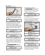
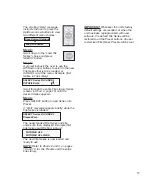
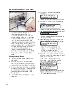
5.

The 

Pump On/Off

pad (Teal) turns the

pump On and Off, just like the

console button. Press and release

the pad to turn the pump On or

Off (a beep will sound). To adjust

pump flow, use either the Variable-Speed

Foot Control or the Up/Down Control Panel

Buttons. When adjusting flow with the Foot

Control, press and hold Teal pad to cycle

through the Flow settings in 10%

increments, from 10% to 100%. A beep will

sound with each incremental change.

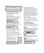
6.

The center 

Variable Pedal

(Blue) can be

operated in either the ‘Variable

or ‘On/Off’

modes, depending on which option is

selected during Setup (refer to Option 6,

page 21).

a. Variable Mode

- Motor speed is

proportional to how far the pedal is

depressed. Depress pedal slowly to

gradually increase speed; release slowly to

gradually decrease speed. 

NOTE:

Variable

is the default when operating the pedal in

Implant

Mode.

b. ON/OFF Mode

- The motor runs only at

‘set’ speed. Foot pedal will switch the

motor ‘On/Off’ when depressed/ released

approximately halfway. 

NOTE:

On/Off is

the default when operating the pedal in

Endo

Mode.

NOTE:

The 

Variable Pedal

can also be

used to reactivate the System from

Standby mode. Press the pedal briefly to

wake up the System and return it to the last

state used. 

AE-7PM FOOT CONTROL

(AEU-7000E only)

The AE-7PM Foot Control is provided as

standard equipment on the AEU-7000E

System. The AE-7PM is used to turn the

motor and pump (when activated) On/Off.

The AE-70V2 Variable-Speed Foot Control

is available on the AEU-7000E System as

an option.

AE-7PM Installation:

Attach the Foot Control cable to the

connector on the back of the Console.

Note keyway on connector. Turn locking

sleeve clockwise to secure cable to

connector.

Fig.13

AE-7PM FOOT CONTROL

(AEU-7000E only)

Handle Installation/Removal:

7.

The Foot Switch Handle may be installed to

allow the user to reposition or move the

Foot Control more easily.

a.

Grasp vertical guide rods and carefully

push handle straight into Switch base (see

Figure 12). To remove, pull rods straight

out.

23

Fig.12 - Handle Installation/Removal

Summary of Contents for AEU-7000E

Page 1: ...AEU 7000E 70V AEU 7000E Implant Endodontic Dental Systems OPERATION AND MAINTENANCE INSTRUCTION MANUAL AEU 7000E 70V System...

Page 2: ...n drilling during osteotomy preparation and implant placement or endodontic therapy This device has been tested and found to comply with the emissions requirements of IEC 60601 1 2 2001 09 These requi...

Page 3: ...ur unit PACKAGE CONTENTS Electronic Control Console P N 120330 AE 230M 40 Autoclavable 40K Brushless Micromotor Autoclavable Motor Holder P N 461561 with Attaching Bracket P N 461562 AE 70V2 Variable...

Page 4: ...rsonnel only WARNING Always follow these guidelines when operating the unit Never touch drills burs files or other handpiece tips when they are still rotating Handpieces should only be attached when t...

Page 5: ...k Australia and New Zealand may require hospital grade plugs Consult local codes WARNING Never use damaged or worn files as they may separate in the root canal WARNING Do not use this device in conjun...

Page 6: ...230M 40 Motor Cord to the receptacle on the lower right front of the con sole Figure 3 by aligning the red dot on the cord connector with the arrow at the top of the receptacle then gently pushing th...

Page 7: ...into the slot located on the front of the pump door c Grasp Luer connector and gently pull outwards then close and latch the pump door Slowly release tension on the Luer connector and allow the O Rin...

Page 8: ...state used 3 Mode Select Button Selects Implant or Endodontic modes of operation Also used during Setup to SELECT menu options a Press SELECT button The System will toggle between Implant or Endodonti...

Page 9: ...RPM 1 2 2 000 80 000 RPM 1 3 3 000 120 000 RPM 1 5 5 000 200 000 RPM 20 1 to 20 7 1 indicating the precise ratio measured This also serves as an indicator that the handpiece has been calibrated 6 Spe...

Page 10: ...em setup ref page 20 warning tones can be enabled to sound when the ASR torque limit is reached c MAX Torque Mode Depressing the MAX A S MAX button until the amber LED illuminates will set the torque...

Page 11: ...Drill Reamer Preset 4 Tap Forward Preset 5 Reverse Tap Preset 6 Install Implant Abutment NOTE Refer to Implant Preset Section on page 13 and Chart 1 on page 14 for complete Preset editing instruction...

Page 12: ...the TORQUE control buttons a Auto Stop and Auto Stop Reverse Torque Modes When in Implant Mode the user can specify an Auto Stop torque limit by depressing the Auto Stop button A S MAX until the gree...

Page 13: ...ion handpieces only into the handpiece as shown in Figure 8 level reaches 75 and 100 of the Auto Stop limit Auto Stop is the suggested mode when tapping and threading implants b MAX Torque Mode Depres...

Page 14: ...Calibration CAL button to activate the integrated Free Run Calibration program Follow the prompts on the display Add Handpiece To Motor Press 1 Next 3 Exit By pressing Preset Button 1 the System will...

Page 15: ...e following editing process the CANCEL button can be pressed to return to the operation screen without saving changes Step 1 Adjust each of the Ratio Speed Torque Flow Rotation Direction and Pump On O...

Page 16: ...e place the cursor under the character and press the INSERT button Note To delete a character in the text line place the cursor under the character and press the DELETE button Step 7 Press SELECT butt...

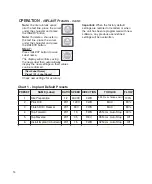
Page 17: ...s All six preset memory buttons can be modified by the user with new files and operating parameters at any time These new settings will overwrite the existing settings including factory defaults In ad...

Page 18: ...ELECT To Save Step 9 Use the Up or Down Yes or No arrow buttons to change the character to the desired letter symbol or numerical value Example FILE NAME YYZ Press SELECT To Save Repeat Steps 8 9 for...

Page 19: ...e 19 until the desired Series appears Step 4 Press SELECT button to load Series into Preset A Wait message appears briefly while the File Series is loaded SELECT Series Or CANCEL Please Wait The newly...

Page 20: ...gh 50 taper File 6 Vortex 06 25 and 30 taper File 7 Vortex 06 15 20 taper Preset Button 5 GT 20 30 40 DENTSPLY Tulsa Dental Specialties GT Series 20 30 40 Files File 1 Accessory 90 70 50 35 12 taper F...

Page 21: ...RIES X 30 04 30 06 300 210 SERIES X 40 04 40 06 300 210 SERIES X 30 08 40 08 300 350 GT PROFILE 04 File Size Speed RPM Torque g cm ACC 90 70 50 35 12 500 700 GT 20 10 GT 20 08 300 312 GT 20 06 PF 35 0...

Page 22: ...ds 1 75 of specified Torque Limit Emits a fast beeping signal 2 100 of specified Torque Limit Emits a slow beeping signal When in Endo Mode a single signal is emitted when the torque reaches the speci...

Page 23: ...Button 1 b To enable Auto Stop Manual ASM and disable ASR press Preset Button 2 5 The next prompt provides a choice of two different time delays before the System enters Sleep Mode wherein the Displa...

Page 24: ...mum five times consecutively When the pad is pressed the sixth time the unit will cycle the torque back down to its first lowest setting For example in Endo Mode repeated pressing of the pad will incr...

Page 25: ...is the default when operating the pedal in Implant Mode b ON OFF Mode The motor runs only at set speed Foot pedal will switch the motor On Off when depressed released approximately halfway NOTE On Of...

Page 26: ...the Main Power Switch on the back panel On 5 The Display will show the following message Press the Yes key on the Control Panel 6 The Display will then show the following message Press the Yes key on...

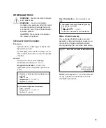
Page 27: ...iately sized sterilization pouch and seal it A Standard autoclaving Gravity displacement method Time 15 min Temperature 132 C 270 F Dry time 30 minutes B Pre vacuum dynamic air removal Time 4 minutes...

Page 28: ...ng sterilization Sterilization Sterilize tubing at 132 C 270 F for 10 minutes FOOT CONTROL The exterior of the foot control may be cleaned by wiping with a soft cloth moistened with mild detergent or...

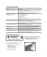
Page 29: ...s on and flow level is sufficient Check that water container seal is completely punctured Make sure the irrigation tubing is properly installed in pump door and flow is in the correct direction Check...

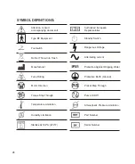
Page 30: ...Throw Into Trash Footswitch Fuse Rating Manufacturer Authorized European Representative Protection Against Dripping Water Protective Earth Ground Motor Direction Preset Step Through Torque Step Throu...

Page 31: ...29 NOTES...

Page 32: ...defect under warranty the purchaser is to notify Aseptico s Customer Service Department promptly Customer Service will provide instructions usually directing that the product be returned for service S...

Reviews: