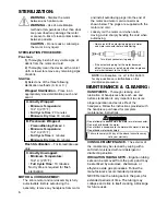
2
ELECTRONIC CONTROL
CONSOLE
SETTING UP THE UNIT:
1.
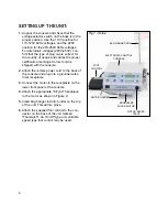
Unpack the console and check that the
voltage selector switch on the back is in the
proper position. Use the 110V position for
110-120V 60Hz voltages, and the 220V
position for the 220-250V 50Hz voltages.
For alternative voltages (220V-250V), con-
firm that the type of plug cap is correct for
the country of usage and carries the proper
certification markings. Correct cord is
shipped with the console.
2.
Attach the remote power cord to the back of
the console and plug into a grounded elec-
trical receptacle.
3.
Connect the motor to the receptacle on the
lower front panel of the console.
4.
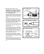
Attach the appropriate "E-Type" handpiece
to the motor as shown in Figure 3.
5.
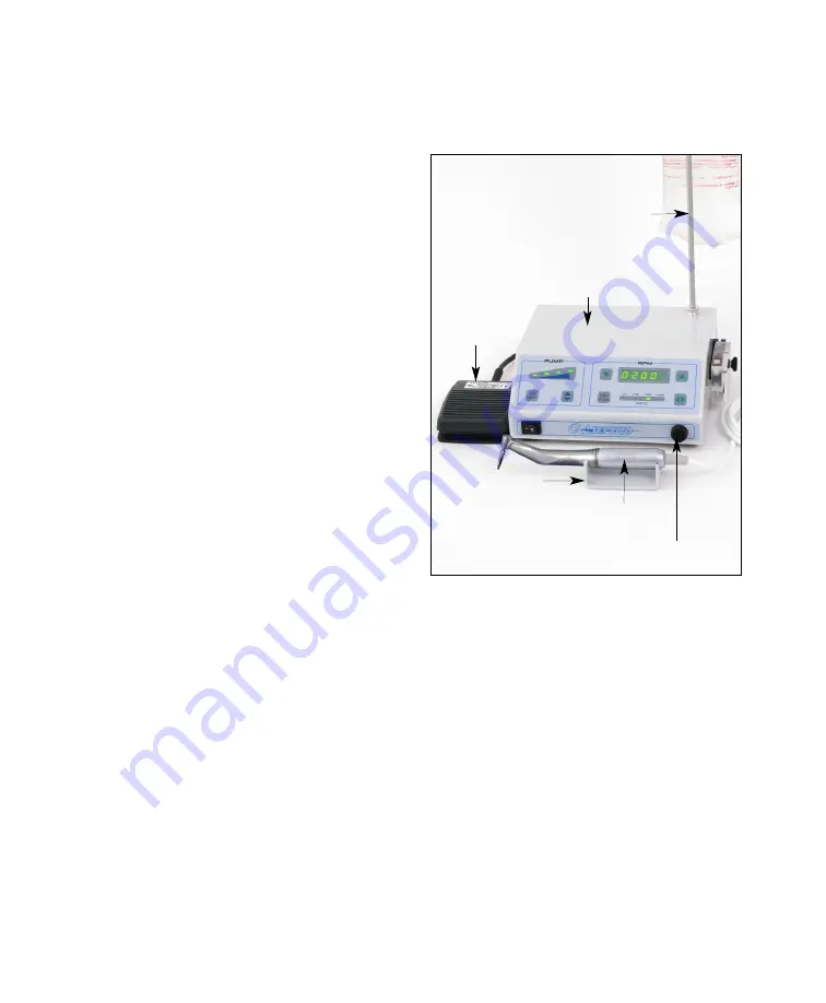
Insert bag hanger rod into holder on the top
of the unit. Thread into place.
6.
Attach the supplied foot control to the con-
nector on the back of the unit marked
"Footswitch". An On / Off type or a variable
speed type foot control may be used.
BAG HANGER ROD
FOOT
CONTROL
BRUSHLESS
MICRO MOTOR
MOTOR HOLDER
MOTOR RECEP-
TACLE
Fig.1 - Setup

