background image

9

AMC‑15

7. 

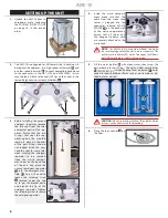
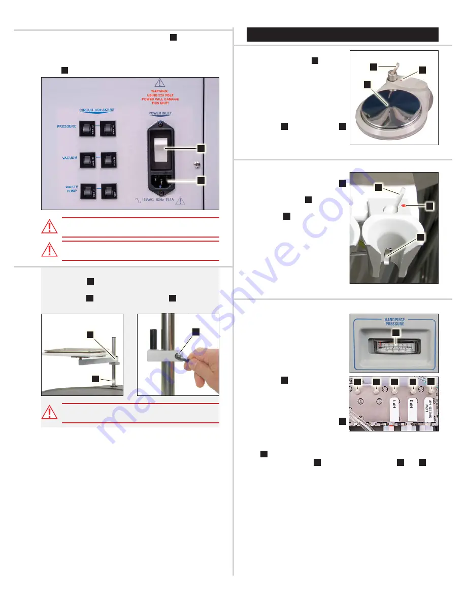
Connect the power cord to the power inlet 

A

 on the rear of 

the cart, then plug the other end of the power cord into a 

grounded electrical outlet of the proper voltage correspond-

ing to the unit version (115V or 230V). Turn the main power 

switch 

B

 to the ON (I) position. 


WARNING:

 Do not connect the power cord to the AMC-15 

in the presence of anesthetics or flammable gases.


CAUTION:

 Do not connect 230V power to a 115V unit to 

avoid circuit breaker damage not covered under warranty.

8. 

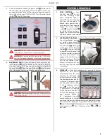
ACCESSORY TRAY —

 To install the 

optional

 accessory tray, 

insert the post 

A

 into the holder on the top lid of the cart. 

Use the included 3/16” hex wrench to adjust the height of 

the pivot block 

B

. Place the end of the arm 

C

 onto the pivot 

block, then place the tray on the other end of the arm.


WARNING:

 Maximum weight capacity of the accessory 

tray is: 10 lb (4.5 kg)

SYSTEM OPERATION

1. 

FOOT CONTROL —

 Press 

the foot pedal 

A

 to acti-

vate the working hand-

piece. Handpiece speed is 

controlled by how far down 

you press the foot pedal. To 

enable water coolant to be 

activated with the foot pedal, 

toggle the water coolant 

switch 

B

 towards the dot 

C


on the foot control, as shown. 

Toggle the switch away from 

the dot to disable water coolant.

2. 

INSTRUMENT HOLDERS —

 Each instrument holder (except 

the syringe holder) provides 

an on/off toggle switch 

A


and an automatic instrument 

shut-off switch 

B

. The toggle 

switch must be ON (towards 

the dot 

C

, as shown) and the 

instrument must be out of the 

instrument holder to operate 

the instrument. (NOTE: Turn 

toggle switches OFF to ensure 

that any instruments that may 

not be fully seated in their 

holders will not turn ON acci-

dentally when the foot pedal 

is activated.)

3. 

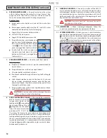
DRIVE AIR —

 Pneumatic handpiece air pressure should be 

adjusted to the pressure 

recommended by the man-

ufacturer. To determine the 

current pressure setting, lift 

the handpiece from the HP-1 

instrument holder and press 

the foot pedal while looking 

at the handpiece pressure 

gauge 

A

 on the front panel. 

If adjustment is necessary, 

lift the top lid on the AMC-15 

cart and lock the hinge in the 

open position. Rotate the 

HP  1 adjustment screw 

B


counterclockwise to increase 

pressure or clockwise to decrease pressure. Repeat this proce-

dure for the HP-2 handpiece using the HP 2 adjustment screw 

C

 and for the LOW SPEED handpiece using the LOW SPEED HP 

adjustment screw 

D

. The 2 remaining screws (

E

 and 

F

) are 

not used. 

Summary of Contents for AMC-15

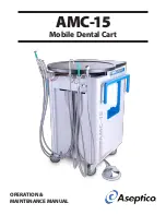
Page 1: ...OPERATION MAINTENANCE MANUAL AMC 15 Mobile Dental Cart...

Page 2: ...d handpiece without water cool ant can cause thermal injury to the patient s CAUTION Observe local regulations concerning disposal of amalgam waste s WARNING Never operate unit or work on patients whe...

Page 3: ...The AMC 15 is available in either a 115V or 230V power supply configuration OPTIONAL EQUIPMENT Purchased Separately PN 730595 Filter Replacement Amalgam Separator PN AA 20A Auxiliary Arm with Accesso...

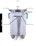
Page 4: ...4 AMC 15 FRONT VIEW Instrument Holders Hinged Top Lid Auxiliary Water Connection Bulkhead Connectors Handpiece Pressure Gauge Waste Indicator Tank Full or Cable Disconnected...

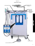
Page 5: ...lant Bottle Selector Bottle Pressure Release Flush Toggle Air Coolant Foot Control w Water Valve Water Supply Bottles Rear Caster w Brake Accessory Arm w Tray optional Optional Equipment shaded Clear...

Page 6: ...ssure Gauge Central Vacuum Cannister Amalgam Solids Trap inside System Pressure Regulator factory set Air Flow Adjustment Block Syringe Flow Adjustment Block Instrument Holder Arm Amalgam Separator By...

Page 7: ...ket Waste Sensor Connector Waste Tank Waste Pump Waste Hose w Clamp Waste Compartment Latch Waste Pump Switch Waste Pump Circuit Breaker Air Tank Purge Valve Air Tank Drain Optional Equipment shaded B...

Page 8: ...tor A into the amalgam man ifold B You will need to loosen the retaining screw C located under the top lid to get the bracket down and around the lip of the amalgam separator Tighten the retaining scr...

Page 9: ...tch B towards the dot C on the foot control as shown Toggle the switch away from the dot to disable water coolant 2 INSTRUMENT HOLDERS Each instrument holder except the syringe holder provides an on o...

Page 10: ...teps for the HP 2 handpiece using the HP 2 valve B A 7 AIR COOLANT Air coolant chip air works in combina tion with the water coolant setting to create a fine mist for the working handpiece Make sure t...

Page 11: ...oses with a disinfectant solution 3 AMALGAM SEPARATOR The optional amalgam separator A is located in the waste compartment The separator filters out particu late matter while the waste water is being...

Page 12: ...TION Do not run saline solutions through the water system saline will corrode the plumbing 8 3 WAY AIR WATER SYRINGE The syringe tip is autoclav able To remove a tip from the syringe press down on the...

Page 13: ...ter coolant valve to the selected handpiece is open No coolant air to handpiece Check that the air coolant toggle is in the ON position Check that the air coolant flow control valve is open Waste pump...

Page 14: ...ith all optional equipment 139 lb 63 kg Shipping Crate Size 30 0 W x 37 0 L x 50 0 H 76 2 cm x 93 9 cm x 127 cm Shipping Crate Weight 72 lb 32 7 kg Power Source 115V version 115V 60Hz 230V version 230...

Page 15: ...tion 2012 Disposing of your old product Each Member State in the European Union EU requires that the waste from electrical and electronic products be disposed of sepa rately from normal household wast...

Page 16: ...chor eye bolts B on the base 5 Place the boxed foot control pedal A under the cart 6 Wrap the cart with pallet stretch wrap 7 Insert the cardboard end panels and side panels into the crate base making...

Page 17: ...17 AMC 15 NOTES...

Page 18: ...18 AMC 15...

Page 19: ...19 AMC 15...

Page 20: ...P O Box 1548 Woodinville WA 98072 1548 800 426 5913 425 487 3157 Fax 425 487 2608 www aseptico com info aseptico com P N 421208 Rev A ECO 14949 06 2020 PRINTED IN THE USA...

Reviews: